Sen oscillating
Only recently I've had time to assemble SEN V18 for my buffalo III DAC.
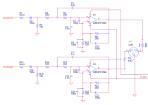
On my scope I have oscillations on left channel 1 Vpp about 30 MHz and 400 mVpp on the right channel. Onboard are el. capacitor value from 220uF to 1000uF and Riv=180, Civ=1100pF, R1=680k, R2=470k, AVcc=3.62V so Vref=1,81V set by trimmer(separate for L and R). Of course I'm using 4x16 NiMH AAA batteries and matched 369V's and boards I've got from Patrick few years ago. Maybe I should increase gate stoppers from 100 ohms to 220 or maybe higher value?
I don't have any capacitors across batteries or any CM chokes.
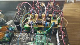
I'll post some photos later.
Only recently I've had time to assemble SEN V18 for my buffalo III DAC.
On my scope I have oscillations on left channel 1 Vpp about 30 MHz and 400 mVpp on the right channel. Onboard are el. capacitor value from 220uF to 1000uF and Riv=180, Civ=1100pF, R1=680k, R2=470k, AVcc=3.62V so Vref=1,81V set by trimmer(separate for L and R). Of course I'm using 4x16 NiMH AAA batteries and matched 369V's and boards I've got from Patrick few years ago. Maybe I should increase gate stoppers from 100 ohms to 220 or maybe higher value?
I don't have any capacitors across batteries or any CM chokes.
I'll post some photos later.
I will be using unbalanced connection for now but later when all bugs are squashed and I find suitable balanced to unbalanced convertor for my amp, I shall move to balanced.
Besides oscillation, problem is hum. The way I have connected is this:
- case is connected directly to earth ground (EGND)
- usb connector shell on the back is therefore connected to EGND
- usb Amanero provides connection from shell(shield)(EGND) to it's pcb gnd by parallel resistor and capacitor.
- Amanero has it's own power supply
- Acko's reclocker (galvanicaly isolated) have all power supplies (3x5V) with dedicated transformer winding and is connected to Buffalo by 4 thin coaxial cables.
- Buffalo outputs is connected to corresponding Sen inputs - signal and ground
- board above Sens provides 2 Vref's for L and R, so Vref for single Sen board is the same. Gnd for Vref circuits has connection only to Avcc's boards. Board also has battery charger regulator (24V), some relay drivers, 4x series diodes + 4x22 ohm for battery packs, and connection to arduino for activating relays. Later I will add some undervoltage battery protector by optocouplers...
- Sens outputs are connected to rca's which is isolated from case(EGND).
- arduino board controlling the DAC, relays and display is isolated from DAC by iso1540 chip.
I've bought some 0805 resistors to replace Sen onboard 100 ohms.
Attachments
Regarding the hum: I found that the the Vref ground reference should not be connected to the AVCC ground but to the power supply ground that feeds the AVCC. This is probably a Placid or something similar upstream. This completely eliminated my hum problem.
Why do you use a trimmer for Vref, and not a fixed voltage divider with precision resistors? It seems like an unnecessary source of error (drift)
Why do you use a trimmer for Vref, and not a fixed voltage divider with precision resistors? It seems like an unnecessary source of error (drift)
Regarding the hum: I found that the the Vref ground reference should not be connected to the AVCC ground but to the power supply ground that feeds the AVCC. This is probably a Placid or something similar upstream. This completely eliminated my hum problem.
Why do you use a trimmer for Vref, and not a fixed voltage divider with precision resistors? It seems like an unnecessary source of error (drift)
Ok, I will connect gnd directly to Placid. Using trimmers are just temporary, i will replace them when I get rid of the oscillation problem.
I have slight hum on my SEN. Are you saying that i shouldn't connect AVCC + and gnd, but rather AVCC + and ground from my 5.25v PSU (SSLV) feeding the Buffalo instead?
It worked for me.
Just to be clear: It is the same ground, only further upstream. So you avoid the return currents that result from buffallo and AVCC operation. I can post a pic when I get home tomrrow.
I've increased gate stoppers from 100 to 220 ohms on the left channel and oscillations decreased to about 50 mVpp. When I move my hand over boards amplitude varies about 10%. In one moment, when I lay my hand on one battery pack and at the same time with the same hand touch bottom support board (earthed), oscillation stops, at least scope doesn't recognize it as 30 MHz anymore, which is btw 1/3 of one of the clock oscillator frequency. But this was measured with gnd wire attached to probe so not exactly valid.
Before start covering battery packs with alu or copper foil I'll try to add 10 ohm and 100 pF in series to agnd on dac outputs that Patrick published in earlier hand drawn es9018s schematic.
Before start covering battery packs with alu or copper foil I'll try to add 10 ohm and 100 pF in series to agnd on dac outputs that Patrick published in earlier hand drawn es9018s schematic.
330 ohm gate stoppers solve the oscillation problem. DC outputs are less than 1mV after about 60 secs. Wiring remains the same and no hum, maybe there is some connecton between hum and high frequency oscillations.
Now I need decent Riv resistors, isolated battery under voltage detection and output relays. I will shunt audio ouputs to ground when batteries are charging, but need some output series resistors, maybe 15-22 ohms.
At the moment arduino is programmed to charge batteries after power on and it can activate/deactivate Sen boards/charging by IR remote. However, there is possibility to forget to turn off Sen boards and in that case some undervoltage protection is necessary.
Patrick used Avago HCNR201 for circlotrons and there is a similar IL300 or TIL300 from TI. However, these thing could use almost 20-25mA for internal led biasing and opamp power so we could check battery voltage periodically by additional optocouplers.
We need one line for powering/charging batteries, another for output shunt relays and the third for opto triggering battery measurement, and, of course 4 analog input lines and little bit of arduino code. Note that after SENs get the power supplies outputs needs time to stabilize at least 20-30s and also if we force charging, outputs needs to be deactivated first.
Hello all. This is my first post here and I am too late to get pcbs to try, so all point to point... I have Buffalo III, and OPPO 105 and I want to try this iv converter. But I have not clear what circuit use, 170/74 or 170 alone or 369V (really I only can get some 372V). Until now I used unbalancer circuit of Broskie with good results, but valves are a problem, so it is necessary search another solution. I have some 170/74 matched pairs 170/74 BL (8.3mA) and some matched 170BL (8.3mA too). If I use these, how many fets in parallel?. Are they are good for 9018?. I know is complex answer me (or tiresome), but I need some initial starting point.
Thanks a lot
Juan Antonio
Thanks a lot
Juan Antonio
Late answer but here we go:
for 9018 you need 369Vs (or 372Vs), 8 of them. For these fets Xen Audio in the past provided V18 pcbs. You need two of these for balanced output with the appropriate heatsinks.
For matching take in account EUVL's comments as posted in #1385
If there are no pcbs available there is ready to etch pcb layout in PFM thread (hmm... can't find the image now, pm me if interested)
Last edited:
I have plenty 2SK369V, but it will take me some time to match them.....
The FETs in the SEN run at full power so heat-sinking is an important issue to address.
Maybe we could convince XEN audio to manufacture a batch of Type 10 sinks for future SEN builders...
The FETs in the SEN run at full power so heat-sinking is an important issue to address.
Maybe we could convince XEN audio to manufacture a batch of Type 10 sinks for future SEN builders...
Lower output level
I wanted to check SEN output THD and then realized that output level is low. Using only one half of each fully populated SEN (unbalanced) for now. I've connected both SEN board inputs to their respective DAC outputs. With single Buffalo III in stereo configuration 2x4 channels, I'm getting only 0,96Veff voltage on both outputs on both L and R channels with full digital sinusoidal input and Riv=180 ohms. It should be about 2Veff. I'm measured it with trueRMS voltmeter and also with scope. DC output is rock steady, below 1mV.
Buffalo III inputs are reconfigured per https://hifiduino.wordpress.com/2012/11/15/buffalo-iii-smart-stereo-input-configuration/ with all output jumpers on buffalo connected.
I2C controller is Arduino UNO. I've checked software register configuration - input remaping, quantizer, all was as it should be.
RollE2k you are right. In ltspice I have 3.34V=3.62V(Vavcc) x 0.924 as amplitude voltage source but actually this is p-p value and amplitude is then half of this. Then Riv should be 360-390 ohms for Vout to be about 2Veff. 2SK369 model that we have is for Idss about 10 mA and if we have Riv=680 like in original V18 schematic, clipping occurs. My fets are about Idss=18 mA so even 680 should be OK. I only have generic metal films and some cmf55 475 ohm, so I'll try these but output will be higher. My amp is directly coupled to SEN (no cap) and it's input impedance is 10k and only has unbalanced input.
Preamp (Gain wire) is not yet finished. Ivy III had pretty low output impedance and now I have to deal with 20x higher impedance and I think cables will then have much greater influence and if I add some discrete output buffer I'll have to add some power supply as well for it. It never ends...
Preamp (Gain wire) is not yet finished. Ivy III had pretty low output impedance and now I have to deal with 20x higher impedance and I think cables will then have much greater influence and if I add some discrete output buffer I'll have to add some power supply as well for it. It never ends...
You can always add a JFET buffer after the R_iv, if it makes you happy.
Just get 2x LSK389 or 2 pairs of matched 2SK170s.
I personally would not worry about using passive.
You want a low pass filter at the R_iv anyhow.
And I presume you don't use cables with 1nF capacitances.
Patrick
Just get 2x LSK389 or 2 pairs of matched 2SK170s.
I personally would not worry about using passive.
You want a low pass filter at the R_iv anyhow.
And I presume you don't use cables with 1nF capacitances.
Patrick
BF862/J111 Cascoded Mirrored
This variant of the SEN I-V uses the available and inexpensive SMD BF862 jfet cascoded by J111, 3 in parallel ... and since we are doing overkill, let's go all the way and mirror balanced I-V circuits.

I'm using SMD film 0.1uF bypass caps but use a really high quality resistor at R3 and R7 attached at the output... thoughts on layout?


There are holes to allow a small finned heatsink to be placed over the 12 JFET array on each side of the board and tied in place with a cord.
Following this comes a similarly mirrored SK filter using Wurcer's discrete OPA (BF862 with hybrid BJT cascode)...
This variant of the SEN I-V uses the available and inexpensive SMD BF862 jfet cascoded by J111, 3 in parallel ... and since we are doing overkill, let's go all the way and mirror balanced I-V circuits.
I'm using SMD film 0.1uF bypass caps but use a really high quality resistor at R3 and R7 attached at the output... thoughts on layout?
There are holes to allow a small finned heatsink to be placed over the 12 JFET array on each side of the board and tied in place with a cord.
Following this comes a similarly mirrored SK filter using Wurcer's discrete OPA (BF862 with hybrid BJT cascode)...
Last edited:
- Home
- Source & Line
- Digital Line Level
- Zen -> Cen -> Sen, evolution of a minimalistic IV Converter