Gate stoppers
Hello everybody,
after a long wait now it's possible for me to finish the SEN V18!
I have a question concerning the gate (stopper) resistor.
Who of you didn't put there a gate resistor in and who not? And the others, also: why?
I'm asking because I would like to understand and because Patrick's document says it is optional. So there has to be a reason for this, I would like to learn.
And in general, what are the pros and cons of using a gate stopper, technically and concerning the sound? And for this circuit? (I know the optimal way would be first without gate stoppers, then measure if SEN oscillates, and if yes, then keep enlarging the resistance as long as there is oscillation. But, I don't have an osciloscope.)
Thank you for your comments!
Best regards,
Matthias
We use gate stoppers all the time.
They help to make sure you do not get oscillation, especially for low capacitance FETs.
There are quite a few discussions about gate stoppers spread over the Blowtorch thread.
You do limit the bandwidth somewhat (as intended).
But as long as you are not too heavy handed, they do not limit the performance on the audio band.
In the F5 Headamp, we are using values up to 1.8k.
But in the SEN, 220R would be a good start.
A second hand cathode ray tube oscilloscope will cost you less than 100€.
It is definitely worth having, in addition to a DMM.
You cannot possibly do DIY properly without.
Patrick
Thanks Patrick for the introduction into gatestoppers, now I can read on from here.
On a few occasions I wished to have a oscilloscope. As I'm now in Brazil, it's not easy to get and it will be roughly double the price of Europe, not to speak us. But do you or qnybody has an recommendation for a digital scope, like Picoscope?
Thanks
Matthias
On a few occasions I wished to have a oscilloscope. As I'm now in Brazil, it's not easy to get and it will be roughly double the price of Europe, not to speak us. But do you or qnybody has an recommendation for a digital scope, like Picoscope?
Thanks
Matthias
I don't use E9018, so I am the wrong person to ask.
But my understanding is that 3.9mA is pk-pk, i.e. +/-1.95mA.
This I presume is per channel (one out of 8).
So as I said, it depends on your configuration.
You can always start using a low value (like 330R) and then measure the output level before deciding on the output level you might want.
Patrick
But my understanding is that 3.9mA is pk-pk, i.e. +/-1.95mA.
This I presume is per channel (one out of 8).
So as I said, it depends on your configuration.
You can always start using a low value (like 330R) and then measure the output level before deciding on the output level you might want.
Patrick
The schematics is correct and is proven to work.
So if you are not getting sufficient signal then either you wired something incorrectly, or
one or more of your 4x 18V independently floating supply is picking up oscillation.
All these have been discussed here and elsewhere (e.g. pinkfish).
Please take time to read through and understand the discussions.
If you feel that you do not have sufficient understanding of basic electronics then
you should try to find someone close to you to help.
And you need equipment to debug, e.g. an oscilloscope.
Patrick
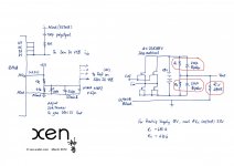
If you have a proper signal generator and a scope, you can check the proper functioning of the IV circuit (version 18), on its own, as follows :
1. Connect the functions generator to the current input of SEN via a 1k resistor.
2. Connect func gen Gnd to R_iv Gnd (not power supply, which is floating).
3. Set the functions generator to output a DC offset of +1.65V, plus an AC sine signal of +/-1V, say 1kHz.
4. Measure voltage across R_iv.
You should be able to measure a 1kHz sine wave with an amplitude of (1mA*R_iv).
If that is the case the IV converter is functioning.
Patrick
- Home
- Source & Line
- Digital Line Level
- Zen -> Cen -> Sen, evolution of a minimalistic IV Converter