We have already tested a JFET-cascoded version which has less distortion of its own, to the degree that we cannot reliably measure anything.
But what is the point if the distortion of the DAC is the limiting factor.
When you use JFETs as the input device, you essentially limit the distortion to mainly 2nd and 3rd.
And after you cancel the 2nd in balanced, mode, you are left with very little distortion at all.
So in terms of performance vs simplicity, the published circuit is still the one to beat, IMHO.
But then of course I am totally biased.
We also tested multiple BJT versions. In the end the SEN is still our own choice.
As Nic said, just build and enjoy the music,
Patrick
I like it a lot. And as you say if the DAC is the limitation what is the point. However, future DACs may benefit from still higher performance I-V. I also have no bias in favor of simplicity per se, although I don't wish to clutter up designs gratuitously either.
And although bipolars are wonderful for many things, I have a deep affection for JFETs. If only they made a few with higher breakdown voltages.
And although bipolars are wonderful for many things, I have a deep affection for JFETs. If only they made a few with higher breakdown voltages.
Agree that some nice P parts would be welcome (I wonder how LIS is coming with the LSA74?).
BJTs as cascodes are somewhat problematic owing to the biasing issues. Enhancement-mode DMOS is also a bit annoying for providing the positive bias and also because, in bootstrapped connections to pump drain-gate displacement currents back into the lower device, you still contend with the body diode and its voltage variability ---although some of that is less deleterious if the preceding JFET has a high-enough impedance at its drain. Worse is if there's a very fast positive voltage change on the upper drain, which can couple through and break down the lower JFET. Admittedly, these are usually small or unlikely effects.
The depletion-mode DMOS parts, the very few of them, don't have a sufficiently large gate-source voltage for most cascoding purposes. And they also have body diodes.
Years ago (thanks here to a reference found by Walt Jung) some high voltage JFETs were made for incorporation in "Fetrons", cascode compound parts groomed as direct replacements for vacuum tubes. In an article about them the author remarks on the difficulty of making high-breakdown JFETs.
You can download the article online free of charge by following the link at post#969.
Courtesy of Jan Didden.
Patrick
Yes, I realized that after I ordered the hard copy. I'd rather pay Jan than download a free article. Thanks.
I think this PCM1794a is too difficult to work with, and maybe not worth the effort. The -6.2mA current offset on the output pins of this DAC has a very serious effect on the Zen type of I/V stage in my sim's, and dealing with that to make the offset zero requires a lot more parts from what I gather on this thread. Someone mentioned that there was a simple way to deal with this, but it'll have to wait until I receive the article in the mail.
I admire your respect for intellectual properties.
But you already bought a hard copy, so you already paid Jan.
On top of that it is an arrangement between me and Jan to make the article available online after 6 months.
So you do not have to feel guilty about it.
You can make the PCM1794 to work with an additional current drain, I think.
That means e.g. an extra battery, a TL431, a NPN and a resistor.
I do not think you will have a thermal stability issue.
The TL431 has a tempco of 50ppm/°C, and you can also use a low tempco resistor.
I do not consider this 4-component circuit to be complicated ?
Please refer to post #784, or Fig.13, 14 of the Fairchild datasheet :
http://www.fairchildsemi.com/ds/TL/TL431A.pdf
Patrick
Last edited:
Yes, I realized that after I ordered the hard copy. I'd rather pay Jan than download a free article. Thanks.
And there a lot of other good things in that issue

There is a question about using the Charger calculator in :
http://www.diyaudio.com/forums/digi...minimalistic-iv-converter-13.html#post2952183
I have attached here a Version 2 which is functionally the same as V1, but with some cosmetic changes.
Download the zip file. Unzip and open the excel sheet as Read Only.
You can change the values of the two cells marked with green background to suit your configuration.
E.g. doubling the mAH capacity would reduce the series resistor by half to double the charge current. etc.
I have double checked to make sure it works as intended, with different no of cells and capacity.
If you can still find any mistake please do not hesitate to let me know.
Patrick
Attachments
Patrick,
The spread sheet does all the correct calculations - if it fed the right information by the user....
The value used in the example is for a nominal 18V pack using two 9V 200 mA batteries in series (i.e. 7 cells/battery = 14 cells, 200 mA).
For a nominal 27V pack using three of the same batteries in series the values to be inserted would be 21 cells and 200 mA.
For a nominal 9V pack using three 9V 200 mA batteries in parallel the values to be inserted would be 7 cells and 600 mA.
I hope I get it right now as I have be over-chargeing a bit lately
Being extremely satisfied with the SEN I will power also the DAC supplies of batteries for coherence and to get the hole thing of the grid. The shunt supplies I am using here are a bit hungry so I need to parallel batteries.
Cheers,
Nic
I was assuming that you use AAA cells, which is loose 1.2V 800mAH nominal.
But the way you count above is correct.
I would advise you use AAA for the V18, as consumption is high at ~45mA.
The 9V block batteries (7 cells in one package) is normally 250mAH.
Will thus only last 4 hours per charge.
Sorry for the confusion. I thought it was obvious.
Perhaps time to buy some AAA cells.
Patrick
Hi Patrick and all
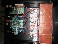
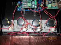
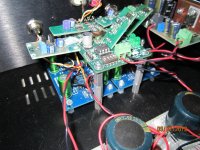
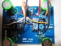
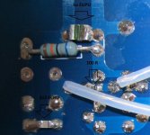
I finally got Buffalo II (ESS9018-based DAC) and SEN up and running a week ago. I managed to arrange things so they interconnect in a close to ideal manner- although they are hard wired together which made assembly, and will make any subsequent upgrades, trickier than usual. I hard wired a ½ AVCC supply on to each SEN board - just two 1 % 1k metal film resistors and a 200u Panasonic FM cap. These are fed directly from the output and ground pin of the relevant AVCC regulator (L and R) on the Buffalo board. Apart from the + and – signal inputs and outputs, the only other connection to each SEN board is a wire, from the ground plane of the Buffalo, close to the outputs, to the ground sides of the IV resistors. The latter are connected together on each SEN board. I used 330 R, Takman MF 0.25W) IV resistors. (The output level is a bit high for my application, and so I will soon change these for Charcroft 150R types. Though as Patrick points out, 680 R is recommended by ESS, and gives the standard output level.) I used 220 u/ 16 V Nichicon ES bipolar caps (soon to be 470 u) in parallel with 1u Panasonic ECPU types, and 3n3 Panasonic ECHU caps across the IV resistors. (The Panasonics are surface mount types).
I used 16 NiMH AAA 900mAh batteries per supply, recharged from a 24 V switch mode supply. To getting the charging conditions correct, I used series 2 W 22R resistors in parallel with 270 R types, preceded by two suitable Schottky diodes (per supply) to drop the input voltage by 1.1 V to the required value. I used a filter on each supply consisting a parallel 4700 u / 16 V Samwha cap in parallel with a 100 u 16V Panasonic FM, preceded (on the negative rail, as the board layout was more convenient) by a Fastron 10mH choke (77A-103M-00). The DAC board is powered by a mains powered Paul Hynes PR3 series regulator (set to 5.5 V) and all the onboard three legged regulators are suitable Hynes types. I used Tiny XLR connectors wired with Van Damme OFC microphone cable(268—002—060) as interconnects
I had delayed construction somewhat, as my (valve) preamp is single ended, and I wanted to avoid using an active BAL to SE converter. To this end I installed 1:1 Jensen JT- P11-1 input transformers in my preamp, terminated wit h the recommended resistor –capacitor network, and directly in front of my (LDR-based) attenuator and line stage . I wired input switching so that both the balanced output from SEN, and the single ended outputs of my tuner and phono stages went through the transformers. As I had hoped, my single ended sources sounded as good, if not better (CMRR improved?) than before. But I became very confused by listening to my IV stage’s- Legato’s- balanced outputs compared with its SE outputs. And listening to its balanced out via the Pass B1 buffer stage I had used between Legato and the op amp- based SE converter stage only confused me further! (All fed, remember, into my new Jensen transformers.) All very different, and, often I preferred the SE outputs- much more macrodynamic and full “based” when needed. Both balanced outs were perhaps a little more detailed and natural, but the buffer stage didn’t seem to improve dynamics. So it was with trepidation that I installed the SEN circuitry....
I did have a slight problem with the latter. A buzz was apparent at high volume settings, despite mains grounding the casework. After a few red herrings I found that touching e.g. the wiring from the batteries and their circuitry stopped the buzzing. I fitted a sheet of thin, adhesive-backed copper sheet to the top of the battery boxes, and the buzz disappeared completely.
The output of my CD transport is galvanically isolated, and its circuitry not earthed, so I thought it best to ground the DAC circuit to mains ground, as- in balanced connection through the transformer- it's not connected to signal ground in the preamp either. Though I’ve since lifted the ground with no audible effect (thoughts anyone?)
The voltage offset on turn was a only a few (~ 3 - 4?) mV, and after about 5 hours operation it was only 0.1 mV L, 0.4 mV R!! You can definitely forget those servos guys
Well that’s about it....
Just teasing. I suppose you’d like to know how it sounds?
Stunning. It’s easily the biggest single step improvement I’ve ever made. To pick out a few things-
The dynamics issue is a thing of the past. Bass is now full, extended and controlled. (I always thought this was feature of just active, voltage gain stages. Another thing I got wrong!)Everything is much more tangible and real. Imagery is much more believable. You can hear all the high frequency harmonics of e.g. solo violin rendered with great accuracy and naturalness. Complex material remains open and it components are easily discernible, without the thickening and distortion often associated with transients and high out levels. Piano sound more natural than ever before, both harmonically and dynamically.
As I said- stunning. And even more so, as, like Nic, I didn’t even think this was a bottleneck in my system. Don’t prevaricate, get soldering!
Thanks Patrick!
Paul N
Attachments
Paul,
My most sincere thanks for your very detailed report of your build.
And I am happy that you seem quite satisfied with the results.
For those who have already had the V18 Evaluation kit, I can only encourage you to start building.
For those who can afford to wait, I can also tell you that our digital expert is looking into our own version of the ES9018 / SEN IV combination.
It will take quite some time, but I guess all good things are worth waiting for.....
Patrick
Last edited:
Paul,
We would like you to help us with the following _
1) Did you use a gate stopper resistor, and if so what value ?
2) I presume you have a soundcard or better still an oscilloscope. In that case kindly remove your battery case shield and have the buzz back please. Then measure the output and find out for us what the frequency of the buzz is.
We only ever had oscillation once at 90MHz. The gate stopper (100R) stops that completely. So we want to understand why you got buzz.
Cheers,
Patrick
Hi Patrick
Yes, I used gate stoppers- 100 R, 0805 package, thick film types (I'm very keen on gate and grid stoppers- my experiences with high Gm valves types ensures this!)
I have a scope, but only a 20 MHz analogue type. I tried to scope the output, but couldn't get a good lock- a lot was going on I think, not just oscillation at one frequency. But, at the time, I was anxious just to effect a cure, and get listening again
I'm not using a battery supply for the digital circuitry. The main pre-regulator board (PR3) is mounted on the side panel, on the RH side at the front in the photograph. The mains transformer feeding- a bog standard toroid for now- is located off board, several feet away (no interwinding shield)- which is why you assumed battery supply I suppose. I very rarely mount transformers onboard. The analogue supply batteries are in 16 battery holders of four batteries each, stacked in a line of four piles of four
Perhaps relevant is something I didn't mention. When I first noticed the buzz, I tried powering the digital circuitry, including the pre-regulator, from a 12 dc switch mode supply. The buzz stopped.
I used 3n3 Panasonic ECHU SMD caps for Civ. They are soldered under the board, directly beneath the Riv, so not apparent in the photograph. I’ll probably fit 4n7 when I change the Riv to 150 R (I have some to hand). Long term I’ll try 6n8, and also no caps, as the Jensen transformer’s response falls off above 100 kHz anyway. On the other hand, it’s located in the preamp some distance away...
The DAC XO is 80 MHz
Hope this helps
Paul N
Attachments
Paul, the fact that you kill the buzz with a SMPS leads me to believe that the course is likely to come from the digital supply.
A buzz is normally low frequency, so perhaps 50Hz or 100Hz (mains pickup).
But it seems that you also have some HF stuff (80MHz) pickup up as well.
At least there is now a solution, so there is no real need for you to change anything.
We shall try to repeat your setup to see whether we notice the same problem and thenhow it can be solved.
For me still very strange. As said, I never had any problem at all.
Thanks for the info,
Patrick
- Home
- Source & Line
- Digital Line Level
- Zen -> Cen -> Sen, evolution of a minimalistic IV Converter