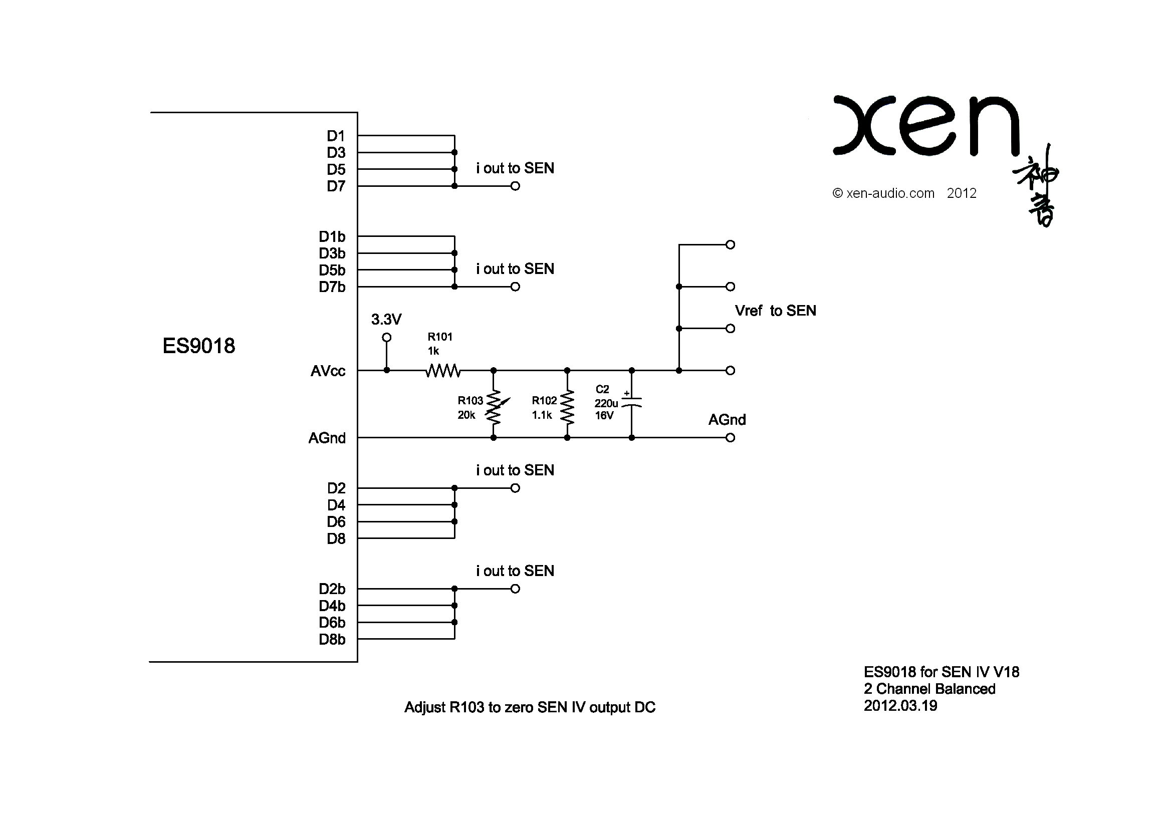
> which voltage for Vref to SEN?
Vref = 0.5x AVcc of ES9018.
See :
http://www.diyaudio.com/forums/atta...n-minimalistic-iv-converter-es9018-sen-iv.png
Patrick
Vref = 0.5x AVcc of ES9018.
See :
http://www.diyaudio.com/forums/atta...n-minimalistic-iv-converter-es9018-sen-iv.png
Patrick
why such a high value for R103? to keep current noise and loading down since its directly across the reference?
Felipe, i was talking about a variation (not much variation) what Nic did, which relies on the jfets being very well matched, if they are you can delete R103 altogether and make R101 and R102 1K (tightly matched, i was suggesting a Zfoil resistor network part) or really 1-2K would probably be ok, higher will have less current noise but higher voltage noise, lower will load the dac analogue reference too much.
Felipe, i was talking about a variation (not much variation) what Nic did, which relies on the jfets being very well matched, if they are you can delete R103 altogether and make R101 and R102 1K (tightly matched, i was suggesting a Zfoil resistor network part) or really 1-2K would probably be ok, higher will have less current noise but higher voltage noise, lower will load the dac analogue reference too much.
Last edited:
So why do we need R103 and why 20k ?
As Nic was the first to test build this, and the only one so far, I wanted to play safe and to include a means to adjust output DC of the SEN IV.
This you can achieve, in addition to good matching, by making Vref adjustable.
To implement this, instead of using 1k for both R101 and R102, I deliberately use 1.1k for R102. When R102 is then paralleled with a 10k resistor, the equivalent resistance will then be back to 1k, and thus Vref is then exactly 0.5x AVcc of ES9018. A 20k linear trimpot has 10k at the min-position, so that is why it should be 20k, and not anything else.
Then you will ask why I would choose 1k for R101 and R102. With AVcc = 3.3V, the current through them is 1.6mA nominal, so it does not load your AVcc excessively. As seen by the JFET gates, it has an output impedance of 1k//1k = 500R even without C2. This is low enough to drive the gates without compromising bandwidth. You may, if you wish, reduce these further to 500R or even 330R without any real drawbacks, as long as your Avcc power supply can deliver an extra 5mA. So feel free to try.
Hope this is clear enough.
Patrick
> which voltage for Vref to SEN?
Vref = 0.5x AVcc of ES9018.
See :
http://www.diyaudio.com/forums/atta...n-minimalistic-iv-converter-es9018-sen-iv.png
Patrick
VRef = 1.65V
why such a high value for R103? to keep current noise and loading down since its directly across the reference?
Felipe, i was talking about a variation (not much variation) what Nic did, which relies on the jfets being very well matched, if they are you can delete R103 altogether and make R101 and R102 1K (tightly matched, i was suggesting a Zfoil resistor network part) or really 1-2K would probably be ok, higher will have less current noise but higher voltage noise, lower will load the dac analogue reference too much.
So as I supposed R103 it's to trimm voltage needed for the VRef to SEN
So why do we need R103 and why 20k ?
As Nic was the first to test build this, and the only one so far, I wanted to play safe and to include a means to adjust output DC of the SEN IV.
This you can achieve, in addition to good matching, by making Vref adjustable.
To implement this, instead of using 1k for both R101 and R102, I deliberately use 1.1k for R102. When R102 is then paralleled with a 10k resistor, the equivalent resistance will then be back to 1k, and thus Vref is then exactly 0.5x AVcc of ES9018. A 20k linear trimpot has 10k at the min-position, so that is why it should be 20k, and not anything else.
Then you will ask why I would choose 1k for R101 and R102. With AVcc = 3.3V, the current through them is 1.6mA nominal, so it does not load your AVcc excessively. As seen by the JFET gates, it has an output impedance of 1k//1k = 500R even without C2. This is low enough to drive the gates without compromising bandwidth. You may, if you wish, reduce these further to 500R or even 330R without any real drawbacks, as long as your Avcc power supply can deliver an extra 5mA. So feel free to try.
Hope this is clear enough.
Patrick
Using R101 & R102 1K can I delete R103 20K trimmer? it's not clear if it's necessary to use or not C2 220uF 16V?
Last edited:
> So as I supposed R103 it's to trimm voltage needed for the VRef to SEN
Yes.
> Using R101 & R102 1K can I delete R103 20K trimmer?
Yes, you have to.
> it's not clear if it's necessary to use or not C2 220uF 16V?
C2 has a different function. It filters any noise at Vref originating from the Avcc.
But you can experiment with values and cap types to see if they make any sonic difference.
Patrick
So why do we need R103 and why 20k ?
As Nic was the first to test build this, and the only one so far, I wanted to play safe and to include a means to adjust output DC of the SEN IV.
This you can achieve, in addition to good matching, by making Vref adjustable.
Hope this is clear enough.
Patrick
perfectly clear, its just nice to get conformations of others design decisions in order to better understand them.
fair enough Patrick, i had mistakenly thought this was made after Nic had tested not before. i figured perhaps it was the reason you gave, but i thought you would have made the fixed resistor higher than 1.1k and lowered the pot value in that case. I understand its just something you roughed out for the benefit of others, with some wiggle room for adjustment given you dont favor the es9018 that much, so havent much experience with it.
i've been playing around with modelling the circuit on the ipad iCircuit, but i cant model a current out dac properly, using a current source in place of the dac and without output impedance or jfet gM factored in, it treats the IV as a short. I wanted to get a sense of how dynamic the load of the gate bias is by feeding a square wave
@nic:
i'm really feeling a lack of a scope at the moment, how do you find the little one nic? was it helpful? ive been looking at those more seriously as an interim solution since Jan reviewed them.
the only thing left to test before i hook it all up is using an A123 battery as the vref feeding LT1028, vs more of a Flea type filtered buffered LTC6655 reference and the Jung 'ultra low noise reference' with AD797
Last edited:
> So as I supposed R103 it's to trimm voltage needed for the VRef to SEN
Yes.
> Using R101 & R102 1K can I delete R103 20K trimmer?
Yes, you have to.
> it's not clear if it's necessary to use or not C2 220uF 16V?
C2 has a different function. It filters any noise at Vref originating from the Avcc.
But you can experiment with values and cap types to see if they make any sonic difference.
Patrick
It's a pleasure to learn with your explanations.
")
Felipe
> ...
And have fun to fit all 6 legs into the PCB at the same time
Cheers,
Nic

I reduced it to 4...like Patrick did.
instead of using PCB tracks i connect transistor legs directly ....got some nice 4 legged compound 2SK372V transistors now
'course a designed new PCBs...just for testing.
Time for a little update.
I have now listened to the SEN with the ES9018 for about a week (a few hours per day) and I am truly impressed. The SEN will stay.
To put it very simply it is as if a bottleneck has been removed from my system - a bottleneck I never new was there
I find myself listening at lower levels now as if a "loudness" button had been pushed. This actually comes together with a clearly expanded dynamic range and frequency extension so it is all positive. I have lately blamed my speakers for being a bit shy in the bass domain, but with the SEN it looks like I just lost an excuse for buying/making new ones
Deep, fast and precise.
The sound is beautiful with voices and the tonal balance is great.
The only area where I am not yet completely convinced is the treble. It does seem just a tiny bit harsh to me. I have the feeling that this depends on the quality of the recordings, but I need more listening to confirm this. I may also try filtering the SEN output a bit more.
I'm currently using the SEN with a modified Buffalo II directly into a set of UcD180HG HxR monoblocks (with regulated supplies) and my French Apertura ALTRA speakers. Attenuation in the digital domain ("volumite").
I look forward to a serious upgrade of the power amp
Initially, when cranking up the volume without music playing, I realized that I was having some kind of low-frequency hum resembling ground loop noise. As grounding is something I have been very careful about I was quite puzzled where I was getting that noise from
As I could certainly not exclude magnetic coupling (one transformer with a single primary) I decided to do as Patrick suggested from day one - use batteries!
I got a bunch of alkaline 9V batteries and the problem was completely solved! The only issue is that it sounds horrible when the batteries run out of juice.....
As I have plenty of power sources in the build I will try NiMH batteries and I may even end up using batteries and regulators. Or maybe separate R-core transformers for each channel.
Before I find the final home for the SEN, I will play a bit with the circuit and see if I can locate any new bottlenecks. A nice thing about these circuits is their extreme simplicity and thus a limited number of components to tweak
I will maybe also try out the CEN in a similar configuration.
Those of you who have the V18 evaluation kit lying around should really try it out. Highly recommended!
Cheers,
Nic
I have now listened to the SEN with the ES9018 for about a week (a few hours per day) and I am truly impressed. The SEN will stay.
To put it very simply it is as if a bottleneck has been removed from my system - a bottleneck I never new was there
I find myself listening at lower levels now as if a "loudness" button had been pushed. This actually comes together with a clearly expanded dynamic range and frequency extension so it is all positive. I have lately blamed my speakers for being a bit shy in the bass domain, but with the SEN it looks like I just lost an excuse for buying/making new ones
Deep, fast and precise.
The sound is beautiful with voices and the tonal balance is great.
The only area where I am not yet completely convinced is the treble. It does seem just a tiny bit harsh to me. I have the feeling that this depends on the quality of the recordings, but I need more listening to confirm this. I may also try filtering the SEN output a bit more.
I'm currently using the SEN with a modified Buffalo II directly into a set of UcD180HG HxR monoblocks (with regulated supplies) and my French Apertura ALTRA speakers. Attenuation in the digital domain ("volumite").
I look forward to a serious upgrade of the power amp
Initially, when cranking up the volume without music playing, I realized that I was having some kind of low-frequency hum resembling ground loop noise. As grounding is something I have been very careful about I was quite puzzled where I was getting that noise from
As I could certainly not exclude magnetic coupling (one transformer with a single primary) I decided to do as Patrick suggested from day one - use batteries!
I got a bunch of alkaline 9V batteries and the problem was completely solved! The only issue is that it sounds horrible when the batteries run out of juice.....
As I have plenty of power sources in the build I will try NiMH batteries and I may even end up using batteries and regulators. Or maybe separate R-core transformers for each channel.
Before I find the final home for the SEN
, I will play a bit with the circuit and see if I can locate any new bottlenecks. A nice thing about these circuits is their extreme simplicity and thus a limited number of components to tweakI will maybe also try out the CEN in a similar configuration.
Those of you who have the V18 evaluation kit lying around should really try it out. Highly recommended!
Cheers,
Nic
If you haven't alreadt tried them, suggest the NeOhm resistors (8G16s) for the o/p I/V resistor - takes about 150 Hrs of play to finally "come good" but they're "something else" (better than my handmade Manganins, in some ways). A somewhat more "laid back" sound to the Vishay Z foils (TC 2575s).
Hi NicTime for a little update.
I have now listened to the SEN with the ES9018 for about a week (a few hours per day) and I am truly impressed. The SEN will stay.
To put it very simply it is as if a bottleneck has been removed from my system - a bottleneck I never new was there
I find myself listening at lower levels now as if a "loudness" button had been pushed. This actually comes together with a clearly expanded dynamic range and frequency extension so it is all positive. I have lately blamed my speakers for being a bit shy in the bass domain, but with the SEN it looks like I just lost an excuse for buying/making new ones
Deep, fast and precise.
The sound is beautiful with voices and the tonal balance is great.
The only area where I am not yet completely convinced is the treble. It does seem just a tiny bit harsh to me. I have the feeling that this depends on the quality of the recordings, but I need more listening to confirm this. I may also try filtering the SEN output a bit more.
I'm currently using the SEN with a modified Buffalo II directly into a set of UcD180HG HxR monoblocks (with regulated supplies) and my French Apertura ALTRA speakers. Attenuation in the digital domain ("volumite").
I look forward to a serious upgrade of the power amp
Initially, when cranking up the volume without music playing, I realized that I was having some kind of low-frequency hum resembling ground loop noise. As grounding is something I have been very careful about I was quite puzzled where I was getting that noise from
As I could certainly not exclude magnetic coupling (one transformer with a single primary) I decided to do as Patrick suggested from day one - use batteries!
I got a bunch of alkaline 9V batteries and the problem was completely solved! The only issue is that it sounds horrible when the batteries run out of juice.....
As I have plenty of power sources in the build I will try NiMH batteries and I may even end up using batteries and regulators. Or maybe separate R-core transformers for each channel.
Before I find the final home for the SEN
I will maybe also try out the CEN in a similar configuration.
Those of you who have the V18 evaluation kit lying around should really try it out. Highly recommended!
Cheers,
Nic
For better treble, it is my experience to replace C7 on the Buffalo ll to a better cap.
This is a simple, minimalisitic charger that we use ourselves for charging NiMH battery packs. We normally leave it always on (hence the low triggle charge current of C/40), and it will take about 8 hours for a full charge.
Open the spreadsheet as read only, and enter input values in the two cells with green background. The rest will be calculated automatically for you.
But there are many modern charger ICs for NiMH, so by all means look around for something more sophisticated.
Patrick
thank you
so you are using 1.5V 400 mAH - how long they are running without charge
Is It a good Idea to have 2 x 9V 250 mAh with Sen
Last edited:
Trying this for PCM 1794
The op-amp I/V stage after my PCM1794 DAC is now measurably the weakest link in my system. So I want to try out this I/V.
I'm planning to use 2 op-amp servos and 2 extra 2SK170s (per channel) to suck out the 6.2mA bias current - see pdf. I'm hoping this will also solve any thermal drift issues.
I'm planning to recycle the 49720 op-amps from the old I/V stage for the new servos.
I've matched Ids (Vds=12V, Vgs=0V) of all quads of 2SK170s. All quads sum to 34.46mA +- 0.01mA.
I have a set of switching power supplies 4 of 24V and 1 of +12V-12V. I also have linear power supplies 4 of 18V and 2 of 12V. I'm hoping the switching ones will be OK.
I'm building it on perfboard with balanced halves back-to-back - see png file showing two halves which will be back-to-back.
ngspice says -135dB 3rd harmonic, 3.978V output.
I've read the thread but haven't read the journal article.
I'm an analog novice.
Any comments on this plan?
Attachments
Please excuse a dumb question.
Relating to the circuits posted here at the beginning of the thread, the output is taken from two points parallel with the NiMH battery supply, which have very low Ri, typically less than 1 Ohm. I don't get how a significant output voltage can be obtained from such a small resistance in parallel with the output.
Relating to the circuits posted here at the beginning of the thread, the output is taken from two points parallel with the NiMH battery supply, which have very low Ri, typically less than 1 Ohm. I don't get how a significant output voltage can be obtained from such a small resistance in parallel with the output.
As explained in the article, the floating supply is in a separate current loop as the signal path, and then the two can be considered so.
The output impedance as well as the IV conversion gain is purely determined by the R_iv.
You can easily set up a Spice model and check this for yourself to help you to understand.
Patrick
The output impedance as well as the IV conversion gain is purely determined by the R_iv.
You can easily set up a Spice model and check this for yourself to help you to understand.
Patrick
Last edited:
As to the PCM1794, I would suggest you replace your entire servo circuit with a simple current sink (to a negative voltage) of 6.2mA adjustable first.
You should first try this out on a breadboard before making any PCB.
You may well find that your current source (depending on design) is stable enough not to require a servo.
See also Ryan's schematics as a reference.
http://www.diyaudio.com/forums/digi...minimalistic-iv-converter-12.html#post2935106
And if you still think you need a servo, then you need one which uses the SEN output as the servo input.
Patrick
Last edited:
Hi,
as Patrick already said, try the simple version first. Its still the lowest noise sink.
You´ll find that this current sink will be the dominant noise source in this circuit anyway. Any more complex circuitry introduces additional noise without giving a practical benefit, since the simple JFET-sink works stable enough and finds it final working point within a minute or so.
jauu
Calvin
- Home
- Source & Line
- Digital Line Level
- Zen -> Cen -> Sen, evolution of a minimalistic IV Converter