Schematics and BoM for Version 18 (for ES9018) do not exist. My laziness / lack of time.
All the details can be found in the GB thread.
Else qusp would be the person to ask. He knows that DAC much better than I do.
You would need 4 pairs of 2SK170/2SJ74 for each CEN V18 PCB instead of 2 pairs (for CEN V2).
And you would need to replace all the 2SK170s in SEN V2 by 2SK369V or BL in SEN V18.
This takes care of the higher current swing and requirement of lower Zin for the ES9018.
Cost, etc also in the GB thread. Please take time to read.
And you may contact MarkLai for availability and ordering details.
Patrick
BJT
Hi..
For no thermal drift. Check the Transistor array THAT340. ;-)
Caad.
BTW, we got a CEN BJT (4 transistors, 3 PSUs) working.
Thermal coupling is crucial.
Quite a bit noisier than CEN or SEN (JFET).
Patrick
Hi..
For no thermal drift. Check the Transistor array THAT340. ;-)
Caad.
As there seems to be little or no progress with the ES9018 version of the SEN IV, I contacted NicMac with a schematics from me, and coached him to make it work. Well, it does work, and the schematics will follow once I tidied it up next week.
Nic agreed to me quoting his email sent a while ago.
"Hi Patrick,
I'm listening to the SEN with ES9018 now and so far its sounding real good!
I only have one balanced channel up and running so serious listening awaits the second channel (and me getting it hooked up to a head-amp).
I build exactly according to your schematics and the DC-offset was easily zeroed out. It stabilizes fairly rapidly (a few minutes) and appear pretty stable (< 1 mV for the first few hours). I will see how it varies over longer times.
Some time ago I got a USB scope (PicoScope 4262) and when I learn to use it I will let you know how it compares to the other I/V-stages I have for the ES9018.
I may be able to send you a couple of photos tomorrow.
Thanks for the detailed help!
Nic"
") Thanks to Nic for supporting. More details to follow in the next few days, including schematics.
Thanks to Nic for supporting. More details to follow in the next few days, including schematics.
Patrick
Nic agreed to me quoting his email sent a while ago.
"Hi Patrick,
I'm listening to the SEN with ES9018 now and so far its sounding real good!
I only have one balanced channel up and running so serious listening awaits the second channel (and me getting it hooked up to a head-amp).
I build exactly according to your schematics and the DC-offset was easily zeroed out. It stabilizes fairly rapidly (a few minutes) and appear pretty stable (< 1 mV for the first few hours). I will see how it varies over longer times.
Some time ago I got a USB scope (PicoScope 4262) and when I learn to use it I will let you know how it compares to the other I/V-stages I have for the ES9018.
I may be able to send you a couple of photos tomorrow.
Thanks for the detailed help!
Nic"
Thanks to Nic for supporting. More details to follow in the next few days, including schematics.Patrick
has anyone used Joahim floating supply http://www.diyaudio.com/forums/digi...minimalistic-iv-converter-46.html#post2770503
I think It Is better than changing batteries everytime
I think It Is better than changing batteries everytime
As there seems to be little or no progress with the ES9018 version of the SEN IV, I contacted NicMac with a schematics from me, and coached him to make it work. Well, it does work, and the schematics will follow once I tidied it up next week.
Nic agreed to me quoting his email sent a while ago.
"Hi Patrick,
I'm listening to the SEN with ES9018 now and so far its sounding real good!
I only have one balanced channel up and running so serious listening awaits the second channel (and me getting it hooked up to a head-amp).
I build exactly according to your schematics and the DC-offset was easily zeroed out. It stabilizes fairly rapidly (a few minutes) and appear pretty stable (< 1 mV for the first few hours). I will see how it varies over longer times.
Some time ago I got a USB scope (PicoScope 4262) and when I learn to use it I will let you know how it compares to the other I/V-stages I have for the ES9018.
I may be able to send you a couple of photos tomorrow.
Thanks for the detailed help!
Nic"
Patrick
Very good news, thanks Patrick & Nic to make it possible.
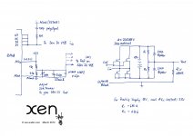
For those who wants to use different voltages, here is a spreadsheet to calculate R1, R2.
Type in Vs of the SEN circuit intended, and the AVcc of the 9018 (nominal 3.3V).
Choose a value for R2, the rest would be calculated automatically.
I normally aim at having R1+R2 around 1M.
Patrick
.
Type in Vs of the SEN circuit intended, and the AVcc of the 9018 (nominal 3.3V).
Choose a value for R2, the rest would be calculated automatically.
I normally aim at having R1+R2 around 1M.
Patrick
.
Attachments
Last edited:
> OK now I understand, so I can use two shunt regulators one +9V for R1 & the other -9V for R2 and both GND connecteds together, right?
Yes, but this "GND" of the two shunts should never ever be connected to anything else, especially anything to do with the ES9018 PCB.
On the other hand, I do not understand why you want to use 2x 9V shunt when you can just use a single 18V supply, whatever it is.
I repeat, anything to do with the floating supply should not be connected to Gnd.
Please see Joachim Gerhard's floating supply schematics if in doubt.
And I strongly suggest you get the circuit to work with 2x normal 9V alkaline batteries first.
When everything works, then you can start fiddling with fancy supplies and what not.
Learn to walk before learning to run.
Patrick
- Home
- Source & Line
- Digital Line Level
- Zen -> Cen -> Sen, evolution of a minimalistic IV Converter