Somewhat complicated but then using fixed rails :
http://www.diyaudio.com/forums/headphone-systems/306350-uthaim-just-fun.html#post5100089
You can consider this as a FET version of:
http://www.diyaudio.com/forums/digi...-minimalistic-iv-converter-5.html#post2718740
which is essentially a high-bias equivalent of the AD844 in open loop mode.
Patrick
http://www.diyaudio.com/forums/headphone-systems/306350-uthaim-just-fun.html#post5100089
You can consider this as a FET version of:
http://www.diyaudio.com/forums/digi...-minimalistic-iv-converter-5.html#post2718740
which is essentially a high-bias equivalent of the AD844 in open loop mode.
Patrick
I demounted all components from one channel and checked them. They all look fine. I measured Idss for all jfets and it was around 16mA for each as expected since the bias was 32mA. When i changed Vgs the current draw decreased as it should.
I measured the resistance of the resistors. I charged the caps by applying a voltage over them and checking that they had that voltage after removing the voltage source.
I have no idea what to check next.
I measured the resistance of the resistors. I charged the caps by applying a voltage over them and checking that they had that voltage after removing the voltage source.
I have no idea what to check next.
The strange thing is I had it on both channels. How do I determine if I have cap leakage?
Maybe it was just a cold solder joint or a short somewhere.
Or cap leakage.
Patrick
My suspicion is that the gate has seen excessive positive voltage due to oscillations of your DAC AVcc.
If the PN junction at the gate is damaged, it might start to leak current at a certain positive voltage below +0.6V.
You might have to bias the gate slightly into positive to see when that happens.
If the JFET is normal then up to 0.2V positive bias should be save.
On a 2SK369V, that should give you more than 10mA Id above Idss, while gate current is still negligible.
Patrick
> I connected the SEN to a signal generator through a 180 ohm resistor to simulate the output from the es9018 (should be 195 ohm but I did not have any). Vref was connected to 1.6 V to get the offset right.
BTW, is the DC of the signal generator also sitting at 1.6V, same as Vref ?
Patrick
BTW, is the DC of the signal generator also sitting at 1.6V, same as Vref ?
Patrick
Interesting, I will try that.
My suspicion is that the gate has seen excessive positive voltage due to oscillations of your DAC AVcc.
If the PN junction at the gate is damaged, it might start to leak current at a certain positive voltage below +0.6V.
You might have to bias the gate slightly into positive to see when that happens.
If the JFET is normal then up to 0.2V positive bias should be save.
On a 2SK369V, that should give you more than 10mA Id above Idss, while gate current is still negligible.
Patrick
Yes, the signal generator dc offset was also 1.6V.
BTW, is the DC of the signal generator also sitting at 1.6V, same as Vref ?
Patrick
I did not have much time today but I biased all jfets of one channel positive. They all looked ok giving Idss+10mA at around 130mV Vgs. I did not measure the gate current though. Hope to find time for that tomorrow.
Measured the fets again and they all seem ok.
Yesterday was a very rainy day and I got around putting together in a box my sen for ESS9018. I am using four lithium batteries XP-L90S (Core SWX XP-L90S V-Mount 98Wh 14.8 VDC Li-Ion Battery XP-L90S)
I have an older model, without usb out.
Now I realized that I overlooked the complication of charging these four batteries at once, while the DAC is in standby and I am reading contrasting information about. Any recommendation on how to tackle this problem ? I was thinking to supply 19 V and make 4 regulators that would supply 16.8 V 1A current limited. Would I put the thing on fire ? I could not understand if the batteries I have protection or not.
Do you know any ready made board or chip to manage these type of batteries. ?
Thanks,
Davide
I have no experience with Li batteries, except that you need discharge balancer as well as proper charger.
There are many ready made solutions for model airplanes and cars.
I suggest you take time to search RC model forums to find out.
The only Li battery pack I have is for topping up smart phones.
It is a ready made solution with everything in one (charging, protection, ....).
Patrick
There are many ready made solutions for model airplanes and cars.
I suggest you take time to search RC model forums to find out.
The only Li battery pack I have is for topping up smart phones.
It is a ready made solution with everything in one (charging, protection, ....).
Patrick
Cen with CCS for TDA1541A
Ryanj, any chance of reposting your schematic? I realize this is very old but getting into this very late...
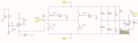
Here are my schematics that i used to adapt the TDA1541A with the Cen current conveyor.
I've been able to get the DC offset on the DAC output quite stable (+-3mV max) but im still evaluating its performance and letting the new parts to settle in. The NTC Thermistor compensates for about 2 to 3mV drift from what i can see so far. It may be benificial to use a Thermistor with a higher Beta value, i used 3977K. 4570K may be better, not sure yet.
An externally hosted image should be here but it was not working when we last tested it.
Ryanj, any chance of reposting your schematic? I realize this is very old but getting into this very late...
Ryanj, any chance of reposting your schematic? I realize this is very old but getting into this very late...
Hi fccn75,
I can't find the original file I posted but here is another one im using for a new PCB design im working on.
The jpg shows a CCS on the left and the SEN circuit on the right.
Ryan
Attachments
- Home
- Source & Line
- Digital Line Level
- Zen -> Cen -> Sen, evolution of a minimalistic IV Converter