AR2, what the resistance (and impedance) of the "primary" in the way you use the trafo?
//
Hi TNT,
As I described somewhere earlier, I use no resistors before the primary. DAC is interfaced with jFet buffer board and than at the buffer's output there is Lundahl 1674. I consider this an optimal configuration in loading DAC and using transformer. Also in this configuration this DAC does not need any termination on secondary, per data sheet and confirmed on my network analyzer. What I suggested for Ian to try just like I did, was to try Lundahl without buffer board, and the only way to safely do it was reversing Lundahl so it it was used as 4+4:1+1. As reversed, secondary provided higher impedance to DAC without need for resistors. The disadvantage is attenuation of the signal. I would not use it this way because of several reasons, but it is the good way in listening the effects of buffer (if any). This transformer could be used as 1+1:4+4 or 1+1:2+2. This is not a good candidate to use Rasmundsen's method where signal is severely attenuated with resistors, and than voltage is amplified through transformer with high ratio. There are several possible ways to do interface DAC with transformer, and doing it with buffer is one of them. It is my preferred method. The only "compromise" is that signal goes through buffer, vs just transformer winding and resistors, but in my case that is through two small jFets and couple of resistors, since buffer is balanced and with no caps in a path of a signal.
The sound is not as thin as with transformer only, and I really do like it.
Best
AR2
Excuse me AR2.. I red your schematic backwards.
Not a problem at all.
Hi,
I'm trying to connect the isolated I2S output of WaveIO into the FIFO input directly.
I get the WaveIO isolator power supply from J5 of the FIFO board according Ian's suggestion in the post #1348.
J5 is labeled as "DC 5V OUTPUT" but instead of 5V there is almost the same voltage as an input DC (6V in my case).
Please, any advise?
Regards,
Andrey
I received the cable UFL RG 178 (8cm) for the master clock,well built cable,clean,in comparison with the 1,37 MM (that of G.B) feeling a greater dynamic range.
mc partagé sur ZimageZ
Ian cards(FIFO-I2StoPCMconvertorBoard) are connected with coaxials cables
coax partagé sur ZimageZ
Amanero-FIFO-I2StoPCM-diyinhk power regulator-A123 replaces the DSP card in the Audio GD Ref 7.1.
ref partagé sur ZimageZ
The implementation is not yet finished,I want to connect the cards with cables UFL,fix properly in the frame,connect BEAGLEBONE Black in I2S directly to the FIFO (when bit perfect).
An externally hosted image should be here but it was not working when we last tested it.
mc partagé sur ZimageZ
Ian cards(FIFO-I2StoPCMconvertorBoard) are connected with coaxials cables
An externally hosted image should be here but it was not working when we last tested it.
coax partagé sur ZimageZ
Amanero-FIFO-I2StoPCM-diyinhk power regulator-A123 replaces the DSP card in the Audio GD Ref 7.1.
An externally hosted image should be here but it was not working when we last tested it.
ref partagé sur ZimageZ
The implementation is not yet finished,I want to connect the cards with cables UFL,fix properly in the frame,connect BEAGLEBONE Black in I2S directly to the FIFO (when bit perfect).
1audio,Femto Clock is a serious misnomer targeted at insecure audiophiles. It all depends on how you measure them. The oscillators that can meet those numbers are not really available for commercial products. When I tried to get them I was told that they were a controlled commodity and I could only sell them inside the US. Typical SOTA commercial performance at 22 MHz works out to about 1.6 pS RMS jitter 10 Hz to 100 KHz. Getting it below that requires very low close in phase noise- -100 dB or less at 10 Hz. Getting that low close in phase noise is very hard and expensive. However phase noise at low frequencies has far less impact on audio. The DAC's internal processes actually limit the performance such that past a pretty accessible level (NDK, Crystek) you won't get improved performance. However good execution will trump even the best conceivable clock used badly. Ian's efforts here are among the best you will find in audio.
I agree on the above points that you explained in a very clear way; I just want to put my two cents in.
Very low noise oscillators are generally not for commercial products, but we are near to obtain all the necessary authorizations for this purpose.
We executed a specific test to compare oscillators with different phase noise profiles and a lower close in phase noise showed significantly better audio quality reproduction.
@all
In other news, I have ordered some prototype PCBs for a PSU design that I hope might be of use to FIFO builders ... two isolated supplies on one PCB (one for each side of the isolator board). LM317 pre-regulator and TPS7A4700 output. By using pre-regulator we get additional PSRR at audio freq but also ability to control volt drop over the TPS7A4700 so that it's not trying to dissipate too much power itself. Will have positions for CRC snubber between transformer and rectifier also. Will post back here with details when I have built and confirmed the prototype is working! I'll also be building some of the tools that Frex has designed for PSU noise measurements so we can see how close we get to datasheet spec for the regulator.
Regards,
Chris
Hi Chris
Do you have some informations about your build
Regards
Phil
Hey Ian
My FIFO board stopped working today, I doubt the onboard regulator failed.
When feed with 6v dc the board outputs 6v to the clock board, and the read on 5v output header(J5) is 6v too.
The power led on board is dimmed too.
Is there any chance I can try to save it?
Thanks
My FIFO board stopped working today, I doubt the onboard regulator failed.
When feed with 6v dc the board outputs 6v to the clock board, and the read on 5v output header(J5) is 6v too.
The power led on board is dimmed too.
Is there any chance I can try to save it?
Thanks
Last edited:
Hi,
I'm trying to connect the isolated I2S output of WaveIO into the FIFO input directly.
I get the WaveIO isolator power supply from J5 of the FIFO board according Ian's suggestion in the post #1348.
J5 is labeled as "DC 5V OUTPUT" but instead of 5V there is almost the same voltage as an input DC (6V in my case).
Please, any advise?
Regards,
Andrey
This is correct what you say. J5 will be the same as the actual input voltage minus some very small drop - much closer to 6V if you power FIFO with 6V.
I did also ask Lucian about this (WaveIO) and he suggested that 6V was within tolerance of the chip. FIFO manual specifies working input voltages between 4.5 and 6.7V. In the end I set the regulator to 5V.
Manual also says FIFO has resettable fuse onboard.. .. ..
Last edited:
1audio - can you describe how and why DAC can't make use of increasing clock performance?
//
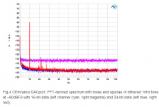
Random jitter shows up as a noise floor in the audio. I will also show as a spreading of the base of a pure tone when reproduced. However Digital audio has a pretty absolute floor for noise, essentially the resolution limit of the bit depth.
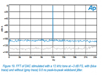
Below- the first picture shows the difference in noise floor between 16 bits and 24 bits. The noise floor drops about 18 dB in this case. The DAC is not capable of a full 24 bits but the idea is clear, there is an absolute noise fllor associated with bit depth (the 16 bit curve illustrates it). The second shows the impact of random jitter; it raises the noise floor. 10 nS random jitter set a noise floor of about -105 dB. Not knowing the resolution bandwidth of the measurement etc. I can't relate the plot to the usual quoted numbers but the relationship is pretty direct- 10X less jitter is a 20 dB reduction in noise floor from jitter. However, once you hit that absolute floor for 24 bits then lower jitter will make no difference in the output.
However deterministic jitter is a different issue. Deterministic jitter is jitter with a specific repeating pattern; either a tone or a collection of tones, like powerline hum. Because its repetitive its possible to detect it even when its below the random noise floor. It needs to be reduces as much as possible.
Audibility of jitter is controversial and the math says it should be much less audible at lower frequencies (as wow is on a turntable). But jitter can be seen as a proxy for good overall digital design. For example crystal oscillators need really good power supplies since the jitter in question is -100 to -170 dB below the carrier, a really large difference. The good news is that an oscillator has no transients if its working right so a low noise supply for a crystal oscillator doesn't need good transient response, just low noise and good supply isolation. Getting the clock distributed and not modulated by other digital circuits and ground noise is a serious design task and more important than getting an oscillator with lower jitter and messing it up with bad distribution or poorly understood isolation.
This is a good primer on jitter: http://www.audiophilleo.com/ja/docs/Dunn-AP-tn23.pdf However some take issues with the points Dunn makes. Here are some other inputs on the issue:
This one shows the spectral contribution of jitter as measured by the AP analyzers: AP High Performance Audio Analyzer & Audio Test Instruments : Service & Support
Here is a reference on measuring jitter with a sound card: Jitter explained - Part 1.4 [English]
Lavry on jitter: http://lavryengineering.com/pdfs/lavry-on-jitter.pdf
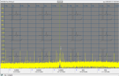
The third picture is a J-Test of jitter on the AKM AKD4399 demo board using the AK5315 SPDIF receiver. The strongest sideband is 60 Hz from the carrier and at -120 approx from the carrier, but its not symmetrical so it may not be a jitter sideband. The sidebands suggest a jitter of about 20-30 pS. This is using SPDIF at the end of a 15 foot coax cable from a PC sound card. I would not write off SPDIF as a means of connecting a digital source to a DAC.
Attachments
This is correct what you say. J5 will be the same as the actual input voltage minus some very small drop - much closer to 6V if you power FIFO with 6V.
I did also ask Lucian about this (WaveIO) and he suggested that 6V was within tolerance of the chip. FIFO manual specifies working input voltages between 4.5 and 6.7V. In the end I set the regulator to 5V.
Manual also says FIFO has resettable fuse onboard.. .. ..
Well I guess I dont know what went wrong now.
The board draws around 230ma at 6v with power led dimmed supplies isolator board(led on) but not spdif board(no led).
Well I guess I dont know what went wrong now.
The board draws around 230ma at 6v with power led dimmed supplies isolator board(led on) but not spdif board(no led).
have you got a USB front end you can try and just disconnect the spdif interface?
have you got a USB front end you can try and just disconnect the spdif interface?
Im running the fifo board with ps(sslv) only now still the same.
Will try with other power source tmr.
Hi Chris
Do you have some informations about your build
Regards
Phil
Hi Phil,
I got the PCBs but haven't had time to order parts or transformers yet. Soon, I hope.
Chris
This is correct what you say. J5 will be the same as the actual input voltage minus some very small drop - much closer to 6V if you power FIFO with 6V.
I did also ask Lucian about this (WaveIO) and he suggested that 6V was within tolerance of the chip. FIFO manual specifies working input voltages between 4.5 and 6.7V. In the end I set the regulator to 5V.
Manual also says FIFO has resettable fuse onboard.. .. ..
Thanks, Ceglar.
I don't take easy ways
and added the voltage regulator based on LT1764 which adjust 6V to 5V exactly.Best,
Andrey
have you got a USB front end you can try and just disconnect the spdif interface?
Im almost sure something is shorted.
Cuz when my board is hooked up with a bench top supply setup to 6v.
Once connected the supply voltage dropped immediately until it reaches its current limit.
Hi Phil,
I got the PCBs but haven't had time to order parts or transformers yet. Soon, I hope.
Chris
Thank you for your answer Chris.
I'll place soonly an order to Mouser.
Let me know if I can help
Regards
Phil
The power supply decides the si570 sound quality. 3.1V seems a bit lower for it. The 3.4V LifePO4 cell is the best PSU I experienced so far for si570. It's worth to give a try it if it is possible
Ian
Right, finally I've got my hands on a lifePO4 cell. Thanks to Ian and dvbprojekt for their assistance so far! I'll report back once i've tried the 570 on lifepo's. Thus far, having compared the 570 and the dual clock boards with crystek 957's (power supply was linear psu + paul hynes minireg for the 570 and a paul hynes regulator for the dual clock board) my preference is the dual clock board....it just sounds more musical to me.
Has anyone so far compared the 570 board powered by lifepo4's with the dual clock board with crystek 957's also powered by lifepo4's?
I'm currently populating an Acko dac pcb that I'm planning to hook up to one of Ian's FIFO kits (hoping that another group buy happens....).
I've found that there are two types of ufl sockets (1.9mm or 2.4mm, info here http://www.farnell.com/datasheets/91524.pdf). Not sure if they take the same cables and want to ensure compatibility with the FIFO boards; which type should I get for my dac board?
Thanks
Ray
I've found that there are two types of ufl sockets (1.9mm or 2.4mm, info here http://www.farnell.com/datasheets/91524.pdf). Not sure if they take the same cables and want to ensure compatibility with the FIFO boards; which type should I get for my dac board?
Thanks
Ray
- Home
- Source & Line
- Digital Line Level
- Asynchronous I2S FIFO project, an ultimate weapon to fight the jitter