... Your good news was my bad news. I no longer keep them for my music after the evaluation. ...
A good news for the next evaluator is my bad news for me either because I need to release it soon.
Good news and bad news. The good news is I have to say those OCXOs are really good. The bad news I’ll tell you later on.
Your good news was my bad news . I no longer keep them for my music after the evaluation.
Ian,
Could you elaborate on what you didn't like? Your first description on page 305 about the "realness" of the music sounded quite promising...
Kind regards
ElEsido
I just wanted to put a quick post out to say that today I jury-rigged Ian's FIFO kit into my dac. Finally after buying it last oct/nov I have had some time. My signal path is now:
Waveio > FIFO board > isolator board > si570 board > dual mono BIIIse's
I'm using a spare placid hd to power the FIFO board and a couple of duracells to give 3.1v to the clock board. I will start looking into more permanent t power options soon but I have never heard my set up sounding so good. Previously I'd noticed occasional harshness with some female vocals but this appears to have go e and replaced with better soundstage and a more analogue/enveloping sound. Sorry, no peer reviewed double blind testing but I love it. Thanks Ian!
Ian,
Could you elaborate on what you didn't like? Your first description on page 305 about the "realness" of the music sounded quite promising...
Kind regards
ElEsido
Hi EIEsido,
The OCXO was good, I like it. It sounds closer to real music, that's why it makes difference from many other clocks. Because of that difference, I need take some time to get familiar with it
. Ian
I just wanted to put a quick post out to say that today I jury-rigged Ian's FIFO kit into my dac. Finally after buying it last oct/nov I have had some time. My signal path is now:
Waveio > FIFO board > isolator board > si570 board > dual mono BIIIse's
I'm using a spare placid hd to power the FIFO board and a couple of duracells to give 3.1v to the clock board. I will start looking into more permanent t power options soon but I have never heard my set up sounding so good. Previously I'd noticed occasional harshness with some female vocals but this appears to have go e and replaced with better soundstage and a more analogue/enveloping sound. Sorry, no peer reviewed double blind testing but I love it. Thanks Ian!
Hi Crom,
Congratulations!
The power supply decides the si570 sound quality. 3.1V seems a bit lower for it. The 3.4V LifePO4 cell is the best PSU I experienced so far for si570. It's worth to give a try it if it is possible
. Enjoy you music
Ian
Thanks Ian, it really does sound fantastic. I've been experimenting further and removed the two Paul Hynes miniregs (that I was using in place of Tridents) from the onboard clocks and hooked up the external master clock from the clock board. I'm undecided about this change. I felt the music lost a little toe-tapping goodness and sounds a little more lean. I had previously played a test track with a long piano sequence in it and the system sounded the most lifelike I had ever heard it. By using the external master clock I felt that it lost a notch of real-ness. Apologies for the crap descriptions but I hope they're understandable!
I take your point about the voltage across the clock. So, I stuck a couple more batteries to provide about 6.2v and then used one of the spare PH mini regs on the clock. Instant difference. Transients much sharper/faster and much more bite to the music. Also some of the lean-ness has been given back to give a bigger body to the music - still not back to levels using the onboard BIIIse clocks. Strange...
I bought a couple of larger (but longer) diameter ufl cables from you so I'll give those a go too, in place of the shorter but thinner grey ones.
I will certainly order a lifePO4 to test out and I'm also going to stick some plugs on the miniregs so that I can easily swap them in and out of the DAC boards and play around with the external clock. I also need to read back through this thread to find out what others have found swapping int/ext clocks.
Apologies for the probably completely dumb question...but...in the si570 manual is says: "As built, it can be connected immediately to an ESS DAC in either the SYNC/ASYNC mode". Can anyone explain what the difference is and how I can change from one to the other?
Thanks,
Crom
Thanks,
Crom
I2S (except MCLK output) from si570 board to Buffalo, and 100mhz buffalo's onboard master clock active = masterclock is asyncronous.
IF 100mhz onboard masterclock is inactive (unpowerd or removed) and both i2s output and MCLK output is fed to buffalo, then master clock is syncronous.
Buffalo III or IIIse should have input pad for external master clock, if I remember correctly.
IF 100mhz onboard masterclock is inactive (unpowerd or removed) and both i2s output and MCLK output is fed to buffalo, then master clock is syncronous.
Buffalo III or IIIse should have input pad for external master clock, if I remember correctly.
essential explanation about syncronous masterclock in sabre dac is here.
http://www.diyaudio.com/forums/digi...e-reference-dac-8-channel-50.html#post1490639
http://www.diyaudio.com/forums/digi...e-reference-dac-8-channel-50.html#post1490639
That's an interesting read, thanks. I'm not sure how to measure phase alignment. However, since that post, the BIIIse does include provision for de-activating the onboard jitter correction. TP warn only to switch it off with a vgood clock source. I tried this and to be honest I couldn't tell any difference but it was pretty late last night and had to have it on quietly! I'll re-try this evening.
Hmmm, I've had some issues creep in...
In my dual mono setup, the master dac is having trouble obtaining lock. After power up, it generally works for about 4 minutes and then at the start of the next song, the L channel (the one output by the master DAC board) flickers the lock LED sometimes once a second but sometimes literally 5-10 times per second. The right channel (the slave dac board) continues to play perfectly.
If I power down the entire dac (waveio, fifo board, isolator, clock board and 2 DAC boards) then it will find a lock 50% of the time again. Perhaps coincidentally, when I power up for the first time (in the evening, say) then it works but stops soon after...heat related???
Things I have tried:
1) Swap the MCLK u.fl connectors around at both the si570 board and the DAC board ends. It appears that the connections are good and this action makes no difference
2) Swap the I2S inputs at both the dac board end and the si570 board end - again, no difference.
What has changed since it was working perfectly:
1) I've moved from directly powering the clock board with 2 duracell batteries and a jumpered regulator connector to using a 6v battery supply and a 3.3v regulator
Ideas:
1) It could be the u.fl cable length? I'm having to use 4" for the I2S and 6" for the MCLK. It could be the different lengths. I have ordered 5cm throughout...I'll report back.
Apart from returning to my original lower voltage (but direct) clock feed I'm out of ideas and would welcome suggestions as to what might be causing the lock problems.
Last edited:
hello
congratulations to ian on a truly great product and dedication to diyaudio
i have just read the whole of this thread after reading the cpm thread and -ecdesigns- monster tda thread
it's people self-less like ian and -ecdesigns- that this forum is the resource and friendly place that it is -thank you.
also big thanks to quasp (and others) for there input of technical information and ideas without which the people who bring us these designs would not know we support and care for them.
quasp - i ( as a newcomer to diy ) agree that it is very annoying when someone asks stupid questions regarding information that could easily be found within 10 seconds on the internet, i.e. things like "what voltage can i feed to this reg" - see the bloody data sheet first then if you have a problem ask!!!
part of the modern gimy gimy culture nobody wants to work for info anymore
anyway OT rant over
i am intending to run the following system -
ian's spdif - fifo - iso - dual xo (crysteks) - i2s to pcm - dual diferential TDA1541A (to -ecdesigns- spec but on my own boards)
i will run this from a mac mini via toslink and a sony CDP-227ES
Q1) if i need spdif output from ian's board i need another iso board in between xo output and spdif input otherwise there's a loop - am i right ?
Q2) sony output from DSP is 48fs will the fifo be ok with this ?
PS i know it will be but sometimes you just need things in black and white
Q3) i intend to use the single clock board ian supplies with the fifo to run the sony in place of oe crystal, and send the i2s to the fifo/dacs using the i2s backdoor. i know that i2s (or the DSP) is not made for transmitting but if i use a differential driver PECL? and custom cable i.e. 6 wires and 3 drivers. So each of ws, bcd and data get there own driver and a +/- wire. Would this be ok ?
PS what crystal do people recommend for 16.**** Mhz as no crystek available
last Q i promise
ian - john (-ecdesigns-) found that TDA dac need only 800mV PP signal swing to function at there best, this is strangely PECL output swing, do you know of any pin compatible PECL drivers for output of signal from pcm board instead of potato 74g ttl levels ?
i ask instead of research because you know the circuit best and can make informed decision - i can always use passive level divider but would like to do it properly
THANK YOU for any reply and the great product and time dedication
i will be adding myself to the group buy shortly
james
If I were you I would try to make sure each dac work properly in stereo mode.
Then make sure I2C connection, firmware setting working properly in dual mono mode.
Thank you for your assistance wktk_smile. I ordered some shorter (10cm) u.fl cables (I tried 5cm but this was unfeasible when trying to connect everything - when I put everthing in a case I may attempt this again) and this has allowed the mclk to successfully obtain and hold lock across both DAC boards.
I have to say that I truly don't like those u.fl connectors!! Expensive and fragile - not good for my clumsy fingers ;-) but imho they do produce better result than just using ribbon connectors.
Clock power up sequence
If I use a clock psu that is tied into my main DAC on/off switch the clock board (si570) does not start fast enough to provide the required 'codes' to the DAC boards. They fail to obtain lock.
I have been experimenting with different clock psu's and using battery power or a kingrex 5v supply everything is fine (I am assuming that this is because I switch the clock board on first). However, if I use a salas board or spare placid HD which is connected to the mains along with the DAC boards then no joy.
There has been some discussion about this here:
http://www.diyaudio.com/forums/digi...553.html?highlight=power+sequence#post3394553
Has anyone else experienced this?
Thanks,
Crom
Dual clock board - own power supply
Hi Ian,
I am looking to set up the dual clock board to see if I have the same issue as the post above but also to compare/contrast the sound. Initially I have the 2 default clocks but I want to start planning a proper comparison and this means looking at the power supply.
so far I have...
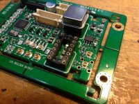
1) Replaced the header with 3 x u.fl sockets (see pic below). I will be using the isolator board before the clock board (although perhaps this isn't the recommended route as it doesn't appear to be mentioned in the manual)?
2) Looked into changing the jumper settings for 45/49MHz XO's. I'm a little confused by the jumper settings. In the manual it says, for example, that for U1 the jumper should be tp3-4 for 22.xxMHz but then in the double-speed manual it says that for U1 the jumper should be between tp4-5 for 22 but between 3-4 for 45MHz. This seems to contradict each other but perhaps I may need to select frequencies with the button too. I'm sure it'll become obvious when I power it up
I can't find an answer to how to power the clock board directly as I'm guessing that it will be needed if I use the isolator board. Oliver from dvbproject asked a similar question and you said that you could pm him the details - I think I need to remove L11 but I didn't want to apply 5v before checking! ;-)
Cheers,
Crom
Hi Ian,
I am looking to set up the dual clock board to see if I have the same issue as the post above but also to compare/contrast the sound. Initially I have the 2 default clocks but I want to start planning a proper comparison and this means looking at the power supply.
so far I have...
1) Replaced the header with 3 x u.fl sockets (see pic below). I will be using the isolator board before the clock board (although perhaps this isn't the recommended route as it doesn't appear to be mentioned in the manual)?
2) Looked into changing the jumper settings for 45/49MHz XO's. I'm a little confused by the jumper settings. In the manual it says, for example, that for U1 the jumper should be tp3-4 for 22.xxMHz but then in the double-speed manual it says that for U1 the jumper should be between tp4-5 for 22 but between 3-4 for 45MHz. This seems to contradict each other but perhaps I may need to select frequencies with the button too. I'm sure it'll become obvious when I power it up
I can't find an answer to how to power the clock board directly as I'm guessing that it will be needed if I use the isolator board. Oliver from dvbproject asked a similar question and you said that you could pm him the details - I think I need to remove L11 but I didn't want to apply 5v before checking! ;-)
Cheers,
Crom
Attachments
OK, sorry for the noise guys...I've done some more digging:
This is backed up by Ian, here: http://www.diyaudio.com/forums/digi...mate-weapon-fight-jitter-127.html#post3208739
The posts around 1246 are not making me confident on hooking it up and I can't find a definitive answer to the clock jumpers. Which is the latest version of the manuals...I have version 1 of each?
@Hochopeper - wld you mind adding the answer to the wiki (or updating links to new manuals if there are any)? I'm happy to help with wiki if ok with you.
The apparent answer is to leave it in place when using the isolator: http://www.diyaudio.com/forums/digi...mate-weapon-fight-jitter-233.html#post3354963if I use the isolator board I think I need to remove L11
This is backed up by Ian, here: http://www.diyaudio.com/forums/digi...mate-weapon-fight-jitter-127.html#post3208739
The posts around 1246 are not making me confident on hooking it up and I can't find a definitive answer to the clock jumpers. Which is the latest version of the manuals...I have version 1 of each?
@Hochopeper - wld you mind adding the answer to the wiki (or updating links to new manuals if there are any)? I'm happy to help with wiki if ok with you.
Last edited:
Hello,
I have a question about the Sis570 clock. I want to build a sound server that resample everything to 32/358,8-384 with sox. I want to connect this server directly with i2s, but as i want to keep the server in a different box, i have to use a lvds transmitter/receiver.
I think i found somthing thas is suitable with the wandboard and community squeeze operating system as it offers the options i want. I ask some precision with the compatibility of the wandboard with i2s and lvds, i they answer this (CSP is the optional card they develop) :
As i'm not sure to understand and not familiar with that, if i want to use this configuration, i have to connect the locale clock to their board and to the dac, could the Sis570 board do that ?
I have a question about the Sis570 clock. I want to build a sound server that resample everything to 32/358,8-384 with sox. I want to connect this server directly with i2s, but as i want to keep the server in a different box, i have to use a lvds transmitter/receiver.
I think i found somthing thas is suitable with the wandboard and community squeeze operating system as it offers the options i want. I ask some precision with the compatibility of the wandboard with i2s and lvds, i they answer this (CSP is the optional card they develop) :
There is an interesting possibility with the CSP hardware, it has an I2S
output and clock input that will work directly with the driver for the
CSP hardware, no software change required. You could build a DAC that
has an ultra low jitter local clock, feed the clock to CSP, take the I2S
out to the DAC and reclock with the local clock in the DAC. You can use
LVDS or standard CMOS for the interface depending on how far the DAC is
from the CSP. If you put both in the same box so the boards are a couple
inches apart you probably don't need LVDS. If they are in separate boxes
a foot or so apart then LVDS is a good choice.
John S.
As i'm not sure to understand and not familiar with that, if i want to use this configuration, i have to connect the locale clock to their board and to the dac, could the Sis570 board do that ?
- Home
- Source & Line
- Digital Line Level
- Asynchronous I2S FIFO project, an ultimate weapon to fight the jitter