Hi guys,
I know this has already been discussed before, but the thread is terrifyingly long and using the search function hasn't helped.
So, how exactly do you implement the power supplying with batteries?
I'm thinking of using cyclon batteries (6V), with a TPS reg. Also, I have some lm10 around and thinking of making a voltage threshold indicator with them. What do you think?
To those who use A123 batteries: Do you have these connected directly on the board?
I use both. cyclon might be one of the best among lead batteries, one of few with medical grade. But you need a low noise LDO. 3.2V LifePO4 battery cell direct power could be better.
Regards,
Ian
I use two battery management V.25, they require two separate 5VDC for each board.
The cause of relay switching repeatedly by I used small capacitor for PSU, when the load current, VDC reduced. Fix with large capacitor .
LifePO4 Battery A123 - setup question
I have been using a generic lifepo4 and just got A123's. Mine don't have any tabs on the negative end and a thread for a screw on the positive. The instructions from A123 recommend that if tabs are soldered that not much heat, if any, be applied. How are people using the A123's attach the tabs or wires to the ends that don't have threads?
From the A123 battery pack design document:
Cell interconnects (tabs) should be neither soldered on the end caps nor attached using extreme heat. A123 Systems recommends tabs be resistance or laser-welded to both ends of the cells.
Thanks in advance.
I need help for group buy order.
Hello. I hope this is the forum for my questions. I will admit I am a newbie. Despite all the reading I've done, it is still difficult for me to understand all the pieces. My project is to setup a media server into a WaveIO to FIFO to I2S PCM to DAC. I found Ian's post:
http://www.diyaudio.com/forums/digital-line-level/192465-asynchronous-i2s-fifo-project-ultimate-weapon-fight-jitter-135.html#post3218811
Ian recommends this configuration to hook up XMOS WaveIO USB interface to FIFO KIT.
I think I need to purchase:
S/PDIF Interface Board
Asynch I2S FIFO
DUAL XO Clock Board
Digital Isolator Board
I2S to PCM Driver to AD1865
I am not sure if I missed anything. If someone is able to help, that would be great. I'd like to purchase all the bits like regulators and so on to make it the best possible. I'm not sure about these options and where they fit into my project.
I want to interface into a DAC which has S/PDIF input to AD1865. My DAC chips are CS8414, 74HC04 and AD1865. I also need help to know what cabling I should order to make hookup of the I2S PCM Driver board to the DAC.
Thanks,
Adrien.
Hello. I hope this is the forum for my questions. I will admit I am a newbie. Despite all the reading I've done, it is still difficult for me to understand all the pieces. My project is to setup a media server into a WaveIO to FIFO to I2S PCM to DAC. I found Ian's post:
http://www.diyaudio.com/forums/digital-line-level/192465-asynchronous-i2s-fifo-project-ultimate-weapon-fight-jitter-135.html#post3218811
Ian recommends this configuration to hook up XMOS WaveIO USB interface to FIFO KIT.
Connecting the isolated I2S output into the I2S backdoor on the S/PDIF Interface Board. The configuration is highly recommended. But you need an additional Vdd for the isolator. You can feed it with the 5V power supply from J13 on the S/PDIF board.
I think I need to purchase:
S/PDIF Interface Board
Asynch I2S FIFO
DUAL XO Clock Board
Digital Isolator Board
I2S to PCM Driver to AD1865
I am not sure if I missed anything. If someone is able to help, that would be great. I'd like to purchase all the bits like regulators and so on to make it the best possible. I'm not sure about these options and where they fit into my project.
I want to interface into a DAC which has S/PDIF input to AD1865. My DAC chips are CS8414, 74HC04 and AD1865. I also need help to know what cabling I should order to make hookup of the I2S PCM Driver board to the DAC.
Thanks,
Adrien.
Hello. I hope this is the forum for my questions. I will admit I am a newbie. Despite all the reading I've done, it is still difficult for me to understand all the pieces. My project is to setup a media server into a WaveIO to FIFO to I2S PCM to DAC. I found Ian's post:
http://www.diyaudio.com/forums/digital-line-level/192465-asynchronous-i2s-fifo-project-ultimate-weapon-fight-jitter-135.html#post3218811
Ian recommends this configuration to hook up XMOS WaveIO USB interface to FIFO KIT.
I think I need to purchase:
S/PDIF Interface Board
Asynch I2S FIFO
DUAL XO Clock Board
Digital Isolator Board
I2S to PCM Driver to AD1865
I am not sure if I missed anything. If someone is able to help, that would be great. I'd like to purchase all the bits like regulators and so on to make it the best possible. I'm not sure about these options and where they fit into my project.
I want to interface into a DAC which has S/PDIF input to AD1865. My DAC chips are CS8414, 74HC04 and AD1865. I also need help to know what cabling I should order to make hookup of the I2S PCM Driver board to the DAC.
Thanks,
Adrien.
Hi Adrien,
If you just want to run AD1865 from I2S sources, then your just need the I2S to PCM converter board.
FIFO KIT is working for improving sound quality. You can included it into your system later on or at anytime you want.
Ian
I have a question on how to best integrate the upgraded version of Peter Daniel's balanced-output DAC using 2 TDA1543 chips with the FIFO.
See details of this upgrade in this thread: http://www.diyaudio.com/forums/audio-sector/187748-pushing-limits-tda1543-nos-dac.html
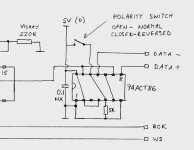
To make a balanced output, one of the two channels of each TDA1543 is fed an inverted version of the data. The stock configuration uses a 74ACT86 (Quad 2-In EX-OR gate). See attached diagram of how this is used to produce the normal and inverted data lines.
I had first thought that the Unversal I2S-PCM board would work here as it as it does produce an inverted data output, but I didn't realize then that the TDA1543 is I2S input only. So the PCM-only output of the converter board would not work.
Then I looked at the FIFO for a similar feature and didn't see one.
Is there a better way to produce this inverted data line, especially in conjunction with the FIFO?
TIA!
Greg in Mississippi
P.S. I am also very interested in how best to integrate the A123 cells while not violating the 'don't solder to the end caps' directive. Any thoughts here too?
See details of this upgrade in this thread: http://www.diyaudio.com/forums/audio-sector/187748-pushing-limits-tda1543-nos-dac.html
To make a balanced output, one of the two channels of each TDA1543 is fed an inverted version of the data. The stock configuration uses a 74ACT86 (Quad 2-In EX-OR gate). See attached diagram of how this is used to produce the normal and inverted data lines.
I had first thought that the Unversal I2S-PCM board would work here as it as it does produce an inverted data output, but I didn't realize then that the TDA1543 is I2S input only. So the PCM-only output of the converter board would not work.
Then I looked at the FIFO for a similar feature and didn't see one.
Is there a better way to produce this inverted data line, especially in conjunction with the FIFO?
TIA!
Greg in Mississippi
P.S. I am also very interested in how best to integrate the A123 cells while not violating the 'don't solder to the end caps' directive. Any thoughts here too?
Attachments
Last edited:
Hello Ian and guys,
It has been awhile for me since I posted here. Ian, I just recently installed my Si570 clock board with no problems. There is slight problem when at 384 KHz, some noise comes out when no signal applied, but than disappears. It also need ssome warm up time. Up to 192 KHz all is cool. But that is not my question. With my previous project where I use FIFO board, I failed to achieve what I originally wanted - all digital crossover. For various reasons I ended up with digital front end and analog crossover.
Now I am starting a new project where I will try to do what I wanted originally, all digital crossover. After very helpful conversation I had with Hochopeper I decided for my crossover to be Titan - LightHarmonics USB to I2S multichannel board and two Acko DACs ESS 9012 boards. Obviously I cannot use FIFO here since there are two DACs, but I was thinking in using Si570 board as master clock for clocking all of the boards in synchronized operation. Titan has possibility of being in the slave mode and Si570 board has as far as I understand 3 MCK outs - two inverted and terminated with 50 ohm and one unterminated and I guess non inverted. I am unclear in the following:
Do I bring to connectors of Si570 World Clock, Bit Clock and one Data signal, and rout all out MCK signals?
Or maybe I do not connect any signals to Si570 board and just pull MCK signals out to each board? Coming out of the Titan Board, World Clock and Bit Clock signals are all the same for all 4 channels, the only difference is data.
Now, there is also thing that Si570 board will not change frequency automatically when in stand alone mode. Does that also stand if world clock and Bit clock signals are delivered to it, so if signal changes its sampling rate Si570 will do it automatically as well?
Thank you
Hi Adrien,
If you just want to run AD1865 from I2S sources, then your just need the I2S to PCM converter board.
FIFO KIT is working for improving sound quality. You can included it into your system later on or at anytime you want.
Ian
Ive been reading your awesome work, but there are too many info
got lost.Im planning to run my AD1865 and TDA1543 . Do I need only the FIFO KIT and the I2S to PCM kit?
Regards!
Hello Ian and guys,
It has been awhile for me since I posted here. Ian, I just recently installed my Si570 clock board with no problems. There is slight problem when at 384 KHz, some noise comes out when no signal applied, but than disappears. It also need ssome warm up time. Up to 192 KHz all is cool. But that is not my question. With my previous project where I use FIFO board, I failed to achieve what I originally wanted - all digital crossover. For various reasons I ended up with digital front end and analog crossover.
Now I am starting a new project where I will try to do what I wanted originally, all digital crossover. After very helpful conversation I had with Hochopeper I decided for my crossover to be Titan - LightHarmonics USB to I2S multichannel board and two Acko DACs ESS 9012 boards. Obviously I cannot use FIFO here since there are two DACs, but I was thinking in using Si570 board as master clock for clocking all of the boards in synchronized operation. Titan has possibility of being in the slave mode and Si570 board has as far as I understand 3 MCK outs - two inverted and terminated with 50 ohm and one unterminated and I guess non inverted. I am unclear in the following:
Do I bring to connectors of Si570 World Clock, Bit Clock and one Data signal, and rout all out MCK signals?
Or maybe I do not connect any signals to Si570 board and just pull MCK signals out to each board? Coming out of the Titan Board, World Clock and Bit Clock signals are all the same for all 4 channels, the only difference is data.
Now, there is also thing that Si570 board will not change frequency automatically when in stand alone mode. Does that also stand if world clock and Bit clock signals are delivered to it, so if signal changes its sampling rate Si570 will do it automatically as well?
Thank you
Hi AR2,
It's great you back to the thread. How are you doing?
I'm thinking about your questions now and will get back to you very soon.
Have a good night.
Ian
Now, there is also thing that Si570 board will not change frequency automatically when in stand alone mode. Does that also stand if world clock and Bit clock signals are delivered to it, so if signal changes its sampling rate Si570 will do it automatically as well?
Thank you
Hi AR2
Regarding the section I've quoted above, I believe that yes it does stand. The reason being that the FIFO processor does all of the thinking in the normal setup and the Si570 just does what it's told by the FIFO. There is a bit of a challenge in using an external MCLK that's not tightly integrated to the transport because you really want it's frequency to change much quicker than any MCU will sense a hardware output then send command to the Si570. Even so I'm not sure the Si570 could be manually controlled in that way because of the way Ian's UART protocol works. Would need some inside knowledge from him on that one I think!
It might be simpler to work out some small daughter board for the LH Titan and clock distribution on it (maybe do two version and compare clock buffers vs passive distribution). What output connections does the Titan offer? I have seen qusp's but only looked at the Titan closely the once, many months (and beers) ago now.
Also, while you're talking about multichannel it always helps to give Ian a gentle reminder that he's toying with ideas for a multichannel FIFO
Chris
Hi AR2
Also, while you're talking about multichannel it always helps to give Ian a gentle reminder that he's toying with ideas for a multichannel FIFO
Chris
Chris,
It seems like you have a habit giving a good advice, and I have a tendency to follow it, haha. I feel bad "gently reminding" Ian on any project because he has been over productive in his achievements that materialize for our pleasure. Just look at his GBs, man half of diyaudio got his board. Another one like Ian is Acko in his steady production of outstanding ideas.
As for Titan, it fancy U.FL and pin headers in the output. Titan has two clocks, in my case Crystek 957 45.xxx and 49.xxx There is also MCK out. I am unclear if you suggested to use Titan as master clock and just distribute that clock to DAC boards? I do have a separate, clock buffer board from Acko. That might be the idea, but I have to figure out how it will work like that. That clock distribution board has XO (Crystek 957 100 MHz) on it, power supply for the clock and fast buffer with 4 outs through U.FLs. XO could be removed and in its place U.FL so I guess that is where I could plug MCK from Titan and disytribute to DACs? But I think that is not really ideal solution. The reason I was thinking about Si570 is because it already has inverted outs, and it makes DAC master and Titan slave. In addition, I have two of those.
I was also thinking about Acko's turbo clock and do not know if that will do what I need since that is stand alone board.
Hi AR2,
It's great you back to the thread. How are you doing?
I'm thinking about your questions now and will get back to you very soon.
Have a good night.
Ian
Thank you Ian! I am fine, very happy to have a time again for diy. Hope you are doing well?
My best
Vladimir
AR2 I think the simplest way would be to do a small PCB for clock buffering for u.fl input of MCLK, BCLK, FSCLK signals and providing w.fl outputs to suit the ackoDAC boards. The PotatoSemi 74G38072A seems a nice fit for that. I've got a few of the 4 way version (38074A) of that chip at home waiting for a few other things to come together so I can give them a run.
It would depend on what the output of the Titan provides (analogue parameters of the gates) to determine if you need to buffer the BCLK and LRCLK because they're going to have a much longer duty cycle than the MCLK, with some damping you may be able to get away without a buffer on those two. Parallel clock lines is an exercise in minimising stray capacitance mostly but using coax u.fl and w.fl you're getting a good start on that.
A board with a buffer adapter to split the signals for the two DAC boards would probably be the neatest solution. As much as I'm hesitant to add yet another PCB to the mix (I'm personally trying to keep my new projects away from becoming the diy 'beast of a thousand PCBs') I think I'd rather that than the complexity of adding the Si570.
That's my vote on the solution at least, I'll keep an ear to the ground to see if Ian thinks up something smarter than I've got in mind
BTW, my 'gentle reminder' to Ian is just a friendly ribbing and intended to be with a giant cheeky grin on my face and I hope Ian knows I mean no malice by anything like that. His productivity is prodigious! You're right, he's contributed far more of his time, knowledge and gear than most in his relatively short time at DIYA. I'm not shy about telling people that Ian's project has inspired me to try some of my own designing. I'm a nerd so I actually have enjoyed the learning side of this thread as much as the great sound that I've got from my FIFO powered headphone system
Chris
It does make a lots of sense. I will hold on Ian to hear what is his opinion. I also posted question about Turbo Clock on Acko's thread. I like the simple approach, and yes, buffered distribution board is something, I believe many would like. In the meantime, I will send you a LightHarmonics data sheet if you do not have one, to give you idea what it has and how is configured. If you would need picture or any measurement, please let me know.
Thanks and appreciate your help very much!
Thanks and appreciate your help very much!
moved form group buy thread:
Yes, in FIFO input jitter is totally rejected and output jitter comes only from FPGA architecture + incoming MCLK jitter (reletively low).
POTATO's FF constant propagation delay has nothing to do with jitter. Sorry, but talking about propagation delay in context of jitter is a mistake. For example clock signal can be delayed 10ns and have jitter of 1ps.
Marek
any re-clocking circuit adds jitter itself.
(...)
Andrea
Its not true. Synchronous reclocking used by Ian greatly lowers jitter of I2S signals. Ofcourse I2S after synchronous reclocking isn't jitter free - it has jitter of XO acumulated with jitter generated by FF, thats why Ian uses POTATO Ghz FF which has one of the lowest induced jitter available.
Other thing is asynchronous reclocking with clock not related to any of I2S signals - it adds jitter but it can be compared to dithering used in computer graphics or in audio and depending of used reclocking frequency can bring some relative improvement (output jitter character not related to source jitter, to content of binary audio signal etc)
Marek
Synchronous reclocking used by Ian is essential since the FPGA adds some jitter to the I2S signal, regardless from the quality of the original signal.
POTATO's FF has a propagation delay around 2ns, so maybe a low jitter but not jitter free.
IMHO, when the BCK is also the MCLK the DAC can be fed directly with I2S signal, without any additional stage that still injects jitter, since the internal logic of the 1541A operates at MCLK frequency.
Andrea
Yes, in FIFO input jitter is totally rejected and output jitter comes only from FPGA architecture + incoming MCLK jitter (reletively low).
POTATO's FF constant propagation delay has nothing to do with jitter. Sorry, but talking about propagation delay in context of jitter is a mistake. For example clock signal can be delayed 10ns and have jitter of 1ps.
Marek
moved form group buy thread:
Yes, in FIFO input jitter is totally rejected and output jitter comes only from FPGA architecture + incoming MCLK jitter (reletively low).
POTATO's FF constant propagation delay has nothing to do with jitter. Sorry, but talking about propagation delay in context of jitter is a mistake. For example clock signal can be delayed 10ns and have jitter of 1ps.
Marek
Of course, I said "maybe low jitter" and not "2ns propagation delay then low jitter" (maybe fast settling), but I said also "not jitter free" (i cannot find anything about jitter in PO74G74A datasheet).
BTW, the debate is about the sense to introduce more stages when probably they are not needed, or, if you want, about the performance of the internal logic of the 1541A when it runs at MCLK against external solutions.
Andrea
tps7a4700 capacitor recommendation
i'm planning on using one of ian's TPA7A4700 regulators configured for 5v to supply the AVDD (analog) pin of my ak4396 dac.
currently the dac is configured like MC7809->AMS1117-5->AVDD.
MC7809 has 100nF+10uF at its output
AMS1117-5 has 47uF at its output
AVDD has 10uF by the input.
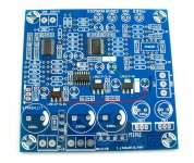
i've attached an image showing what my plans are to fit the TPA7A4700 regulator in place of the AMS1117-5. i will lift the input pin of the AMS1117 to disable it, and remove the 47uF capacitor to provide vout and gnd connections for the TPA7A4700 pcb. vin will come from a jumper wire attached to the output of the MC7809 (using the "accessible" input pad of another regulator; see red trace).
my first question is: any issues with running it with a long vin jumper wire like that?
second: looking at the provided schematic for the TPA7A4700 pcb, there are optional oscon input and 1uF film (i think?) capacitors.
which of these, if any, would benefit this application? and if 1uF is already a good value for the output, what capacitance would be ideal for the input? is oscon still a good choice for this application given that it's for the analog vin of the ak4396, or should i look for something like a nichicon KA/KZ?
here's some ideas so far:
output:
BC Vishay MKT370 1uf/63v
input:
Sanyo OSCON SEPC 470uF/16v
Nichicon Muse KZ 100uF/25v
thanks,
-matt
i'm planning on using one of ian's TPA7A4700 regulators configured for 5v to supply the AVDD (analog) pin of my ak4396 dac.
currently the dac is configured like MC7809->AMS1117-5->AVDD.
MC7809 has 100nF+10uF at its output
AMS1117-5 has 47uF at its output
AVDD has 10uF by the input.
i've attached an image showing what my plans are to fit the TPA7A4700 regulator in place of the AMS1117-5. i will lift the input pin of the AMS1117 to disable it, and remove the 47uF capacitor to provide vout and gnd connections for the TPA7A4700 pcb. vin will come from a jumper wire attached to the output of the MC7809 (using the "accessible" input pad of another regulator; see red trace).
my first question is: any issues with running it with a long vin jumper wire like that?
second: looking at the provided schematic for the TPA7A4700 pcb, there are optional oscon input and 1uF film (i think?) capacitors.
which of these, if any, would benefit this application? and if 1uF is already a good value for the output, what capacitance would be ideal for the input? is oscon still a good choice for this application given that it's for the analog vin of the ak4396, or should i look for something like a nichicon KA/KZ?
here's some ideas so far:
output:
BC Vishay MKT370 1uf/63v
input:
Sanyo OSCON SEPC 470uF/16v
Nichicon Muse KZ 100uF/25v
thanks,
-matt
Attachments
Also, while you're talking about multichannel it always helps to give Ian a gentle reminder that he's toying with ideas for a multichannel FIFO
Chris
+1
currently the dac is configured like MC7809->AMS1117-5->AVDD.
MC7809 has 100nF+10uF at its output
AMS1117-5 has 47uF at its output
AVDD has 10uF by the input.
correction, by default the AMS1117-5 is fed from a (nearby) MC7812, not the pictured MC7809. i would like to jumper the TPS7A4700 vin over to the MC7809 though to take the load off of the MC7812, because the MC7812 is also used for the opamps in the output stage.
thanks,
-matt
Hello Ian and guys,
It has been awhile for me since I posted here. Ian, I just recently installed my Si570 clock board with no problems. There is slight problem when at 384 KHz, some noise comes out when no signal applied, but than disappears. It also need ssome warm up time. Up to 192 KHz all is cool. But that is not my question. With my previous project where I use FIFO board, I failed to achieve what I originally wanted - all digital crossover. For various reasons I ended up with digital front end and analog crossover.
Now I am starting a new project where I will try to do what I wanted originally, all digital crossover. After very helpful conversation I had with Hochopeper I decided for my crossover to be Titan - LightHarmonics USB to I2S multichannel board and two Acko DACs ESS 9012 boards. Obviously I cannot use FIFO here since there are two DACs, but I was thinking in using Si570 board as master clock for clocking all of the boards in synchronized operation. Titan has possibility of being in the slave mode and Si570 board has as far as I understand 3 MCK outs - two inverted and terminated with 50 ohm and one unterminated and I guess non inverted. I am unclear in the following:
Do I bring to connectors of Si570 World Clock, Bit Clock and one Data signal, and rout all out MCK signals?
Or maybe I do not connect any signals to Si570 board and just pull MCK signals out to each board? Coming out of the Titan Board, World Clock and Bit Clock signals are all the same for all 4 channels, the only difference is data.
Now, there is also thing that Si570 board will not change frequency automatically when in stand alone mode. Does that also stand if world clock and Bit clock signals are delivered to it, so if signal changes its sampling rate Si570 will do it automatically as well?
Thank you
Hi Vladimir,
I’m sorry for getting back too late. I was tied up with the GBV. Fortunately my wife lands a hand.
I could be wrong, but if I understood your project with correct, my multi-channel/DSD FIFO would be your perfect solution. It will have 14 channels at I2S mode and 8 channels at DSD mode. I already finished the DDR memory controller, the FIFO management and other basic modules, but I have to design the DSD receiver, transmitter, zero signal detector and other related sections. I’m working on an Altera FPGA verification KIT now, will transfer to my own PCB after passing all the simulation and real test. The only problem is I don’t know when I will finish this project. I won’t want it slow down your project.
Si570 clock board works in this way: together with the FIFO board, they work as a close loop frequency control. So, there is a Mega8 on the Si570 board to perform the management. In order to avoid introducing any noise into clock board, Mega8 works in a very special way: sleeping mode with only a couple of uA power consumption. When FIFO found can’t lock to an input Fs, it will wake up the Mega8, Meaga8 will figure out what frequency needs to set by pick up the Fs measurement result from FIFO via SPI bus. Then, the Si570 driver will set a new frequency, and at same time xFs will also be sent into FIFO. Mega8 will go into deep sleep mode again after doing the above jobs. It seems a bit tricky, but there is no any secret code, if hochopeper found a bit difficult to control the si570 board, it's all because of the special working mode. You need a real time software to communicate with it at the window time
.Si570 board can work standalone as a master clock for sure, but I just cannot figure out how to switch between frequencies without the supporting of FIFO.
The three I2S input signals on the clock board are just for re-clocking, they are equal, so you can feed any signals rather than limited to any specified one. All three MCLK output are inverted to the flip-flop clock which can be accessed form one pin of R28.
Or, might be, think about if there is any possible we make two stereo FIFO working in parallel mode, one for master and the other is slave…. Please let me know your idea.
Some time, I need switch gear for a while. I was trying to fix iMac at board/BGA level last month. Now we have three iMac27s, form 2009 to 2011 models, one for myself, one for my son and other one for my mother in law
. All of them are fixed from “as parts no working iMac”. I think I should open a thread on iFixit now.Thanks guys, I’ll focus on the multi-channel/dsd project the next, it would be really exciting project
.Regards,
Ian
Last edited:
- Home
- Source & Line
- Digital Line Level
- Asynchronous I2S FIFO project, an ultimate weapon to fight the jitter