Some additions:
I've reread the Linear Audio (which actually was vol.4) article. They mention osccilation with the ad797 at 2.2MHz in jung/didden superregs, not there with the ad825. Mine have the AD825. Furthermore it seems like theyve been built with the sjostrom bom, I bought mine as completed modules. Used caps look like panasonic FR but not 100% sure there.
Also before I used simple LT1085 powersupplies for waveio/fifo as in attached photo, replacing those with C-sjostrom reg was a significant change for the better, for both waveio and fifo this time")
yes, I know the regs will be fine if he built them (I already know he built them). hes used a non low impedance electro there for that reason, but you are connecting it to low impedance caps. the 797 or 825 doesnt have much meaning here, the opamp isnt driving the load directly, hes talking about internal loop stability with that comparison
yes, I know the regs will be fine if he built them (I already know he built them). hes used a non low impedance electro there for that reason, but you are connecting it to low impedance caps. the 797 or 825 doesnt have much meaning here, the opamp isnt driving the load directly, hes talking about internal loop stability with that comparison
You mean on the fifo then? Hmm there seems to be a 680uF on its input. Maybe I should put some resistance before it? I guess I really should buy a signal generator/scope some day huh
Help needed.
Hey folks
I've been trying to hook up a raspberry pi i2s to the fifo board to make a network stream player.
Now I think Im an inch away from it. According to raspberry pi forum we could have i2s pin outs like this:
GPIO P5 TDA1541A
28 pin 3 --- BCLK
29 pin 4 --- WS
31 pin 6 --- DATA
na pin 8 --- GND
I installed i2s backdoor kits and connected
r22---pin 8
r23---pin 3
r25---pin 6
r24---pin 4
The interface board is switched to i2s input (3 lights on).
When playing 96k audio file I have the lock light on with empty and full off
When playing 48k audio file I have only empty light on.
And there wasn't any output from XLR what so ever.
After this I tried it with hiface opt input no output either.
Did I broke the output board?(again?)
Last edited:
Hi guys,
am trying to manually set the Si570 clock board to group 1 and 2 (10 and 20MHz clock range), but it doesn't work. I'm circling the LED to one of them, but after the saving it jumps back to group 3 (40MHz range).
What could possible be wrong?
My setup: WaveIO > FIFO > Isolator > Si570
am trying to manually set the Si570 clock board to group 1 and 2 (10 and 20MHz clock range), but it doesn't work. I'm circling the LED to one of them, but after the saving it jumps back to group 3 (40MHz range).
What could possible be wrong?
My setup: WaveIO > FIFO > Isolator > Si570
yep, the fifo (and the XMOS if you are powering that with another one), I would probably use an inductor/ferrite, but yes a resistor will do. Since its just driving more regulators anyway, the low impedance and sensing of the super-regulator is of little utility
Thanks for the pointer qusp, I've tried a resistor, there does seem to be an audible difference but too slight to make out if it's an improvement or not. I guess the best thing for me to do would be actually buying some decent measuring equipment
Solely going by ear is not reliable enough to draw reliable conclusions. However on the to do list which needs to be judged by ear since I lack funds for measuring equipment is bigger and/or multiple chokes and different arrangements.DAC Noise
Hi all,
I have a version of the FIFO I bought last July, including the SPDIF input PCB. I'm using a CCD-957 crystal. The unit is driving I2S into a TDA1541A DAC chip. I'm using a PC/CAS, with a TOSLINK feed.
The FIFO has been working great, up until a few weeks ago, where a strange noise from the left channel has been getting progressively worse. It sounds like "scratching", some "pops" and other assorted noises. It starts randomly, sometimes lasts for a few seconds, stops - and may not come back even after hours of listening. Other times, like last night - well, it just kept coming back every few minutes. As you might guess, it's causing a lot of grief for my speakers, as the noise comes in quite a bit higher than the audio signal and causing the drivers to oscillate wildly.
I've ruled out the DAC PCB as it was doing it on my old PCB, before I rebuilt it a couple of weeks back (for unrelated reasons) I've checked the connections to the FIFO PCB assembly and all seems to be in order. I've also checked the signal path out of the DAC, to the output coupling caps (which I've swapped) and all is OK there. Always out of the left channel.
Can anyone suggest what the issue might be? Occasionally, when the noise is occurring, the LED lock LED on the front panel flickers, leading me to believe it's somewhere on the digital side, but wondering how it would always end up appearing on one channel
Thanks...
First, I should apologize for my break-in here as I am not a user of this FIFO.
(I wait for a DSD supporting version.)
However, I am very interested in quality of a master clock, I2S & DSD signals and I hope my recent experience on a certain power supply system applied to a clock generation circuit might be somewhat useful to people here.
Last week, I tried a "Solar Cell Panel" based power supply on the combination of Chiaki's SDTrans SD memory card player and ES9018 Dual Mono DAC. This power supply is reported in another thread.
http://www.diyaudio.com/forums/digital-source/142562-microsd-memory-card-transport-project-62.html#post3569285
I applied the PS to 6 power sections on the player+DAC one by one confirming its effect. When I applied the PS to the clock section of ES9018 Dual Mono DAC, where dual Crystek CCHD-950, 40s MHz oscillators are used, I just got very the same and strong impression edbk expressed above.
I have realized the importance of quality of PS for a clock circuit again.
I think some people here have Lithium Ion Polymer Batteries as a reference.
Though I have not compare the solar cell panel PS with the Lithium ion batteries, I imagine the solar cell panel one might give a better result.
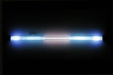
By the way, the solar cell panel PS employs commodity Krypton light bulbs as a light source and a simple shunt regulator (TL431+2SA1941) as a voltage regulator. You can build it in a DIY manner very easily.
I am sure I can guarantee its performance.
(I wait for a DSD supporting version.)
However, I am very interested in quality of a master clock, I2S & DSD signals and I hope my recent experience on a certain power supply system applied to a clock generation circuit might be somewhat useful to people here.
... I'm using Sjostrom superregulators to power waveio/fifo with fully seperated clc powersupplies. The powersupply has a very large impact on the sound, quite surprised by how much for basically a D/D converter! I have tried nichicon muse, panasonic fc, mundorf ag, elna silmic 2, they all sound quite different, also interesting that clc sounds better then c before the sjostrom superreg (cleaner/more LF impact), even copper or silver wiring in the powersupply is audible, I can offer no explanation for this, I've gone back and forth numerous times over several weeks and have had friends over to make sure I was not imagining things..
The dual crystek setup sounds significantly better in my system. Cleaner, clearer, more/finer detailed, better soundstaging, tighter more powerfull lows/more impact. ...
Last week, I tried a "Solar Cell Panel" based power supply on the combination of Chiaki's SDTrans SD memory card player and ES9018 Dual Mono DAC. This power supply is reported in another thread.
http://www.diyaudio.com/forums/digital-source/142562-microsd-memory-card-transport-project-62.html#post3569285
I applied the PS to 6 power sections on the player+DAC one by one confirming its effect. When I applied the PS to the clock section of ES9018 Dual Mono DAC, where dual Crystek CCHD-950, 40s MHz oscillators are used, I just got very the same and strong impression edbk expressed above.
I have realized the importance of quality of PS for a clock circuit again.
I think some people here have Lithium Ion Polymer Batteries as a reference.
Though I have not compare the solar cell panel PS with the Lithium ion batteries, I imagine the solar cell panel one might give a better result.
By the way, the solar cell panel PS employs commodity Krypton light bulbs as a light source and a simple shunt regulator (TL431+2SA1941) as a voltage regulator. You can build it in a DIY manner very easily.
I am sure I can guarantee its performance.
Last edited:
I saw that, I really dont get it, lights of this strength radiate considerable amounts of noise, even the wrong LED or plain incandescent light can have detrimental effect on a wide bandwidth system and these will have many times the noise power. intentionally introducing another noise source into or just nearby a clock supply… I think i'll leave it as it could easily affect more than just that circuit. High quality regulators after batteries or even well filtered pre-regulated DC type supplies, should render any difference insignificant.
its for sure an interesting/novel, if rather inefficient way to get DC power. very inventive!
just googled it, Krypton can be radioactive in some forms and has wide spectral wavelength. this makes it a wide bandwidth noise source, this wide spread will make it useful for this purpose of generating power as it gives off more power to be harvested, but that aspect also makes it more of a pollutant noise-wise. it gives off red, green and fairly blue/UV/white light, other than the red, the highest noise types
Krypton
Attachments
Last edited:
qusp, What a misunderstanding you have!
I just emphasize two points.
1. An incandescent lamp emits the least electromagnetic wave noise when we compare it to a fluorescent lamp and a LED lamp. That's the reason why an incandescent lamp is used in a special room for RF measurement.
(Of course, it emits a impulsive noise at a timing of turn ON/OFF because of a rush current. That is not a problem.)
Please check the noise an incandescent lamp emits by using an AM radio actually.
The spectrum of light emitted by a krypton light bulb is known as very similar to that of a solar light. It is based on a black body radiation of heated filament. No electric discharge event is involved.
Even if you have any concern on the use of a krypton lamp, you have a definite solution. You can simply use a solar light, instead.
Can a solar light be a known noise source?
2. A solar cell panel power supply system has the following good points
A. AC-power transformer-less, rectifier-less, smoothing-circuit-less (i.e. capacitor-less)
B. No mechanism that may introduce any ripple involved
C. A high-speed response of photoelectric effect in a semi-conductor that is faster than that of an electrochemical reaction in a usual battery can be expected
D. A solar cell can be regarded as a constant current source under a constant amount of incident light and a constant temperature
E. Providing a complete galvanic isolation with a mono-directional signal(energy) flow
"Listening is believing"!
Last edited:
Bunpei, its not a problem that needs solving … no misunderstanding, well maybe yours
notice I said EVEN an incandescent light, after LED, bright white light, blue light and UV light itself is a noise source if you have other LEDs in the circuit, or wide band amplifiers. kryton 85, the type used, is a radiation source, as is the fluorescence. krypton is not incandescent
no I dont misunderstand that part, I know the advantages, thats why I said it was interesting, but listening alone is fooling… but none of them are any advantage over post regulated quality batteries
if you can still hear a difference between good battery with regulated supply and your solar thingy, your regulator is not working properly. its that simple, your PSRR and ripple should be so low as to be meaningless and as long as your regulator is feeding a clock on the dac board, other noise sources on the board and all around in the air will dominate.
is sunlight a source of radiated noise? if its being emitted from a source right next to you absolutely it is!! its a radiation, EMI and RF noise source over a broad spectrum, not just the visible wavelengths either if it wasnt for our atmosphere, we would burn to a crisp, I think that falls within the definition of a radiated and electromagnetic noise source yes...
capacitor less? that would be interesting… you want to let all the HF noise in the area have its way with no decoupling caps?
batteries have this also, of course there is a chemical reaction that makes noise, but photo cells are not completely noise free either.
then post regulate the battery, are you comparing to the solar cell without the shunt regulator? no you arent
and the difference to a battery is? apart from the charging, but of course for the cost and massive size of this thing, I dont think you would have trouble building a battery supply that never ran out, just a switch to auxiliary while primary battery charges. I dont even think battery is needed, but thats the comparison you made.
there is no fluctuation from the ripple on the AC source for the light? how is it much different to a capacitor for light? so your power source for the light will need to be fairly good still.
this is different to a battery?
also whether you like it or not, there are parasitic noise currents everywhere
as I see it its a novelty and its huge and I dont need it, but I dont get it honestly, it just seems like a solution to a problem that is not really there. I do find it interesting from a novelty point of view and its a different solution to the problem, but thats where my interest ends. solar cells are at best 15-20% efficient, my dac already burns 100W, I dont need more overkill
notice I said EVEN an incandescent light, after LED, bright white light, blue light and UV light itself is a noise source if you have other LEDs in the circuit, or wide band amplifiers. kryton 85, the type used, is a radiation source, as is the fluorescence. krypton is not incandescent
no I dont misunderstand that part, I know the advantages, thats why I said it was interesting, but listening alone is fooling… but none of them are any advantage over post regulated quality batteries
if you can still hear a difference between good battery with regulated supply and your solar thingy, your regulator is not working properly. its that simple, your PSRR and ripple should be so low as to be meaningless and as long as your regulator is feeding a clock on the dac board, other noise sources on the board and all around in the air will dominate.
Can a solar light be a known noise source?
is sunlight a source of radiated noise? if its being emitted from a source right next to you absolutely it is!! its a radiation, EMI and RF noise source over a broad spectrum, not just the visible wavelengths either if it wasnt for our atmosphere, we would burn to a crisp, I think that falls within the definition of a radiated and electromagnetic noise source yes...
A. AC-power transformer-less, rectifier-less, smoothing-circuit-less (i.e. capacitor-less)
capacitor less? that would be interesting… you want to let all the HF noise in the area have its way with no decoupling caps?
B. No mechanism that may introduce any ripple involved
batteries have this also, of course there is a chemical reaction that makes noise, but photo cells are not completely noise free either.
C. A high-speed response of photoelectric effect in a semi-conductor that is faster than that of an electrochemical reaction in a usual battery can be expected
then post regulate the battery, are you comparing to the solar cell without the shunt regulator? no you arent
D. A solar cell can be regarded as a constant current source under a constant amount of incident light and a constant temperature
and the difference to a battery is? apart from the charging, but of course for the cost and massive size of this thing, I dont think you would have trouble building a battery supply that never ran out, just a switch to auxiliary while primary battery charges. I dont even think battery is needed, but thats the comparison you made.
there is no fluctuation from the ripple on the AC source for the light? how is it much different to a capacitor for light? so your power source for the light will need to be fairly good still.
E. Providing a complete galvanic isolation with a mono-directional signal(energy) flow
this is different to a battery?
also whether you like it or not, there are parasitic noise currents everywhere
as I see it its a novelty and its huge and I dont need it, but I dont get it honestly, it just seems like a solution to a problem that is not really there. I do find it interesting from a novelty point of view and its a different solution to the problem, but thats where my interest ends. solar cells are at best 15-20% efficient, my dac already burns 100W, I dont need more overkill
Last edited:
QUSP-
Krypton is used in light bulbs because its an inert gas and won't interact with the hot filament. The radiated spectrum of the bulb is quite broad (black body radiator at approx 3200 degrees K) but its modulation (the noise in the light) is very small since the thermal mass of the filament is pretty high relative to the energy input fluctuations. You won't see the 60 Hz power ripple on the output of the panel.
You seem to be responding to the Krypton hype as though its special. Light bulbs have used argon and krypton Krypton - Wikipedia, the free encyclopedia since the 1920's to conduct the heat out and make them easier to deal with, no vacuum. Its only good marketing to to take something obsure and make it special.
I explored this idea about 20 years ago. Back then the solar panels were not efficient enough and the heat output would make this seem just silly. Now it seems almost practical if incredibly un-eco.
I would put caps on the supplies, the impedance of the shunt regulator will increase with frequency (not what you want) and the panel is a current source so you need some source for HF current.
Stabilizing the light source would also be a good thing if not essential.
If this seems almost rational why not use a thermopile and a heating element as a power source?
And then this would be the ultimate audiophile power source- really exotic, expensive and unobtainable Radioisotope thermoelectric generator - Wikipedia, the free encyclopedia
SiS570 and lifepo battery power
The lifepo4 battery charger I got charges the battery to a tad more than 3.6vdc. The battery stays above 3.2vdc for a little while. If I setup the SiS570 board for direct battery feed, jumpering TP5/TP3, the 3.3-3.6vdc from the battery (until it drains into the "normal" 3.2vdc output) is acceptable or is it too high?
I did get the regulator from Ian but I'm installing battery power direct. Thanks in advance.
I got 3.43V from my fully charged LifePO4 cells (no load). It will run from 3.4V to 3.2V in most of working time. Though Si570 Clock board normally works no problem with 3.6V power, but I still suggest you keep your LifePo4 for a while after it been fully charged, to see if the voltage can drop a little bit lower, or try a better charger.
Regards,
Ian
Hey Ian
Would you mind to look into my problems here?
Help needed.
Hey folks
I've been trying to hook up a raspberry pi i2s to the fifo board to make a network stream player.
Now I think Im an inch away from it. According to raspberry pi forum we could have i2s pin outs like this:
GPIO P5 TDA1541A
28 pin 3 --- BCLK
29 pin 4 --- WS
31 pin 6 --- DATA
na pin 8 --- GND
I installed i2s backdoor kits and connected
r22---pin 8
r23---pin 3
r25---pin 6
r24---pin 4
The interface board is switched to i2s input (3 lights on).
When playing 96k audio file I have the lock light on with empty and full off
When playing 48k audio file I have only empty light on.
And there wasn't any output from XLR what so ever.
After this I tried it with hiface opt input no output either.
Did I broke the output board?(again?)
I was wondering if the output side of the interface board is broken or higher up in the data chain.
Now that I connected the battery manager to the clock my charge numbers look just like yours! But when it was under no load they were higher. So it's working as intended and sounding the best my system has sounded ever. Thanks again Ian.I got 3.43V from my fully charged LifePO4 cells (no load). It will run from 3.4V to 3.2V in most of working time. Though Si570 Clock board normally works no problem with 3.6V power, but I still suggest you keep your LifePo4 for a while after it been fully charged, to see if the voltage can drop a little bit lower, or try a better charger.
Regards,
Ian
Now that I connected the battery manager to the clock my charge numbers look just like yours! But when it was under no load they were higher. So it's working as intended and sounding the best my system has sounded ever. Thanks again Ian.
Good to know that, congratulations!
Now you can try some good clocks and enjoy your music.
Ian
- Home
- Source & Line
- Digital Line Level
- Asynchronous I2S FIFO project, an ultimate weapon to fight the jitter