I forgot, subjective storytelling rules, if its heard and seen it must be so... get rid of those nasty low inductance MLCC from around the Si, quickly evil SMD ceramics. sorry this is nonsense, the si is MADE from thin film and very likely has chosen MLCC type and thin film caps inside. leaded film caps are completely powerless for HF and this board does operate at HF. it has onboard logic and DSP of sorts, did you remove the MLCC from around the flip flops that operate up into microwave territory too? was there any logic used to choose the capacitor values to match the frequencies of interest that need to be suppressed?
sorry it just gets to me when people make declarations like this that cannot be true unless there is a preference for error, removing the only caps that can keep such frequencies suppressed from the board and replacing with inductors (they will look like inductors at VHF) cannot make objective improvements and its not a matter of opinion.
then replacing them with pretty film caps without measurement or simulation and declaring improvements from this simple random act... when this board went through; what was it Ian 4 generations of PCB prototyping and extensive measurement over the period of almost a year, including extensive simulation and listening before official release?
Last edited:
While its absolutely true that phase noise above the sample rate doesn't matter (it has no place to go) the conversion of phase noise to audio increases with frequency. In pure noise terms the maximum sensitivity to phase noise would be around 3-4 KHz (maximum hearing sensitivity falls off both going up and down). Hearing phase noise/jitter directly at 20 Hz or even 100 Hz would be very difficult. Its the equivalent to wow and flutter at those low frequencies only orders of magnitude lower. The AES standard measures phase noise from 100 Hz to 20 KHz.
Deterministic jitter (spurs in the phase noise spectrum) are much easier to identify and probably hear since they are constant "tones". The close in ones would be a form of vibrato if they are large enough.
Really low close in phase noise is very difficult to get and expensive. But the techniques will also lead to lower overall phase noise.
The power supply I designed was specifically for crystal oscillators to get the lowest noise possible.
Here is a quick crash course in jitter relevance (keep in mind the ADC/DACs this is about are targeting RF in the 100 MHz range so the requirements are 1000X what audio would require) http://www.cerc.utexas.edu/msrf-seminar/y2005/tk050215_slides_kuyel.pdf
The problem is not hearing phase noise below 10 Hz, but the conversion error due to phase noise.
The impressions I reported (not only mine, but from a listening group) are from a comparative test between 2 oscillator using a CD Player, Marantz CD 94 if I remember correctly.
The first oscillator was an OCXO with a phase noise around -130dBc@10 Hz and -94dBc@1Hz, the second one is a simple XO (7 components only) using a very good At-cut crystal with the same phase noise at 10Hz but with -103dBc@1Hz. The simple XO performs much better as the impressions reported.
It's not so difficult to reach good performance in phase noise close to the carrier, tipically the real problem is the quality of the crystal.
The problem is not hearing phase noise below 10 Hz, but the conversion error due to phase noise.
Perhaps you can explain this more? How does the jitter at 10 Hz or below affect the conversion? It would be a form of frequency modulation but of very small magnitude. Ladder DAC's will react differently from delta-sigma dacs to jitter.
I would really like to see the circuit of the oscillator with 7 components with such low phase noise. And any crystal specs you may have to share. In a CD player I would guess its running around 11 MHz. For an AT crystal it would be a 3rd overtone crystal most likely.
not just phase noise, but noise and EMI/RFI radiation in general will be effected if you remove all the usefully targeted SMD decoupling caps from the clock which is not just a clock and the clock buffers that operate above 1ghz. given all of this is directly connected to ground thats shared with both clock and dac analogue stages, as well and adding leaded caps that will operate more effectively as radiating RF aerials than capacitors, I think we create a situation that does not cause obvious audible improvements and could possibly create 2nd order effects that are broadcast from all the cables connected to the board.
While its absolutely true that phase noise above the sample rate doesn't matter (it has no place to go) the conversion of phase noise to audio increases with frequency. In pure noise terms the maximum sensitivity to phase noise would be around 3-4 KHz (maximum hearing sensitivity falls off both going up and down). Hearing phase noise/jitter directly at 20 Hz or even 100 Hz would be very difficult. Its the equivalent to wow and flutter at those low frequencies only orders of magnitude lower. The AES standard measures phase noise from 100 Hz to 20 KHz.
Deterministic jitter (spurs in the phase noise spectrum) are much easier to identify and probably hear since they are constant "tones". The close in ones would be a form of vibrato if they are large enough.
Really low close in phase noise is very difficult to get and expensive. But the techniques will also lead to lower overall phase noise.
The power supply I designed was specifically for crystal oscillators to get the lowest noise possible.
Here is a quick crash course in jitter relevance (keep in mind the ADC/DACs this is about are targeting RF in the 100 MHz range so the requirements are 1000X what audio would require) http://www.cerc.utexas.edu/msrf-seminar/y2005/tk050215_slides_kuyel.pdf
Last edited:
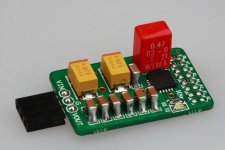
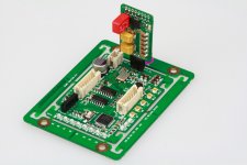
Thanks zapio for sharing your experiences with us, and thank your for your effort. I'm very interested in a closing picture of your mod Si570 board, is there any possible you post some?
Have you every try to replace the 1uF CNR (C10) on the TPS7A4700 LDO board with a film capacitor? I did some test last week and the result was quite amazing.
I'm looking forward to your good news.
Regards,
I removed the following capacitors : C5, C6, C20, C19, C46, C17 on top and C18 , C30 on bottom side. The effect was the opposite of that expected due to deterioration of the quality of decoupling Si board.
Ian
Perhaps you can explain this more? How does the jitter at 10 Hz or below affect the conversion? It would be a form of frequency modulation but of very small magnitude. Ladder DAC's will react differently from delta-sigma dacs to jitter.
I would really like to see the circuit of the oscillator with 7 components with such low phase noise. And any crystal specs you may have to share. In a CD player I would guess its running around 11 MHz. For an AT crystal it would be a 3rd overtone crystal most likely.
I cannot explain better, I can presume only, these were impressions (subjective of course). From the objective point of view there was the same CD player, the same power supply (12V for both), the only difference was the oscillators with the same performance in phase noise above 10 Hz and different phase noise below 10 Hz.
The TDA1541 seems to react better with lower phase noise close to the carrier.
I cannot tell anything about delta-sigma DAC, never tried with them.
The XO is a simple Clapp oscillator, I'm currently testing several circuit (Clapp, Colpitts and Butler), and I have to do appropriate measurement of each configuration, then I'll publish the results.
The crystal is a specially polished AT-cut, fundamental at 11.2896 MHz.
Modding TPS7A4700 low noise regulator
Based on powering Si570 clock board form a 3.2V LifePO4 battery direct as a reference recently, I found there still some space to improve the performance of TPS7A4700 low noise regulator.
1. Upgrade the noise reduction capacitor CNR
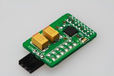
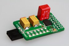
The first priority is to upgrade the noise reduction capacitor C10 to a nice film capacitor. Remove 1u MLCC C10, replace it with a WIMA 0.47u/63V capacitor on C11 position which was especially reserved for this purpose. The one I use was:
WIMA P/N: MKS2C034701C00KSSD, or
Mouser P/N: 505-MKS2.47/63/10.
This capacitor works as a filter of the control loop of the internal voltage reference, so it will decide the noise performance of TPS7A4700 itself. Though the MLCC is good at high frequency, but it’s not as good as a nice film capacitor at low and middle frequency, together with the piezoelectric effect, film capacitor is no doubt the winner for this position.
The result is quite positive. Improving on sound quality of the Si570 clock board was very obvious. It worth to try different candidates or large capacitive to find out which one is the best of best.
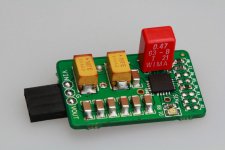
2. Upgrading the output capacitors
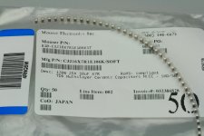
I found TDK has a new technology ‘soft termination’ series 10u/25V 1206 MMLC. Comparing with normal MLCC, it’s expected better on reducing the effect of vibration and shock (piezoelectric effect). They are only available on Mouser.
TDK P/N: C3216X7R1E106K/SOFT
Mouser P/N: 810-C3216X7R1E106KST
I replaced all 10u MLCC: C1,C2,C3,C4,C5,C8,C12 with this now technology capacitor, the result is also positive, but not as much as replacing the CNR.
Or, you can stack the new capacitors on top of the old ones. It will sound a little bit different.
Somebody also mentioned good result on film output capacitors. But I don’t have that big film capacitors, please give a try if you have.
3. Upgrading the input capacitors
I tried to replace the two AVX 100u/25V TANT capacitors with a DIP 270u/16V SP OS-CON solid capacitor. Though it sounds pretty good, but I still like the sound of AVX at this position. So I get back to AVX. Please let me know if you can find some better choices of input capacitors.
Ian
Based on powering Si570 clock board form a 3.2V LifePO4 battery direct as a reference recently, I found there still some space to improve the performance of TPS7A4700 low noise regulator.
1. Upgrade the noise reduction capacitor CNR
The first priority is to upgrade the noise reduction capacitor C10 to a nice film capacitor. Remove 1u MLCC C10, replace it with a WIMA 0.47u/63V capacitor on C11 position which was especially reserved for this purpose. The one I use was:
WIMA P/N: MKS2C034701C00KSSD, or
Mouser P/N: 505-MKS2.47/63/10.
This capacitor works as a filter of the control loop of the internal voltage reference, so it will decide the noise performance of TPS7A4700 itself. Though the MLCC is good at high frequency, but it’s not as good as a nice film capacitor at low and middle frequency, together with the piezoelectric effect, film capacitor is no doubt the winner for this position.
The result is quite positive. Improving on sound quality of the Si570 clock board was very obvious. It worth to try different candidates or large capacitive to find out which one is the best of best.
2. Upgrading the output capacitors
I found TDK has a new technology ‘soft termination’ series 10u/25V 1206 MMLC. Comparing with normal MLCC, it’s expected better on reducing the effect of vibration and shock (piezoelectric effect). They are only available on Mouser.
TDK P/N: C3216X7R1E106K/SOFT
Mouser P/N: 810-C3216X7R1E106KST
I replaced all 10u MLCC: C1,C2,C3,C4,C5,C8,C12 with this now technology capacitor, the result is also positive, but not as much as replacing the CNR.
Or, you can stack the new capacitors on top of the old ones. It will sound a little bit different.
Somebody also mentioned good result on film output capacitors. But I don’t have that big film capacitors, please give a try if you have.
3. Upgrading the input capacitors
I tried to replace the two AVX 100u/25V TANT capacitors with a DIP 270u/16V SP OS-CON solid capacitor. Though it sounds pretty good, but I still like the sound of AVX at this position. So I get back to AVX. Please let me know if you can find some better choices of input capacitors.
Ian
Attachments
I cannot explain better, I can presume only, these were impressions (subjective of course). From the objective point of view there was the same CD player, the same power supply (12V for both), the only difference was the oscillators with the same performance in phase noise above 10 Hz and different phase noise below 10 Hz.
The TDA1541 seems to react better with lower phase noise close to the carrier.
I cannot tell anything about delta-sigma DAC, never tried with them.
The XO is a simple Clapp oscillator, I'm currently testing several circuit (Clapp, Colpitts and Butler), and I have to do appropriate measurement of each configuration, then I'll publish the results.
The crystal is a specially polished AT-cut, fundamental at 11.2896 MHz.
Ha Andrea,
So Jocko put the wind up you, so to speak, and you have tried some of his
suggestions.
") Yes he is a cranky bugger at times but there's a lot of
Yes he is a cranky bugger at times but there's a lot of experience behind those words.
I am presuming you have now measured the AT cut oscillator you designed?
And are you saying it has beaten the OCXO subjectively speaking?
As you know I already sell 11.2896 MHz SC-cut OCXO's based clocks, but I
get very mixed subjective results. IME just low phase noise is not whole
story. I have to also use right components for PS and squaring circuit
otherwise the damn thing still doesn't sound quite right. It's a right royal
PITA and I am the first to admit I don't fully understand this all.
I'm now on about rev 5 of the clocks and I -think- these ones sound great
but have to do the usual go back to original reference for a while and see
how it all stacks up.
Ha Andrea,
So Jocko put the wind up you, so to speak, and you have tried some of his
suggestions.
experience behind those words.
I am presuming you have now measured the AT cut oscillator you designed?
And are you saying it has beaten the OCXO subjectively speaking?
As you know I already sell 11.2896 MHz SC-cut OCXO's based clocks, but I
get very mixed subjective results. IME just low phase noise is not whole
story. I have to also use right components for PS and squaring circuit
otherwise the damn thing still doesn't sound quite right. It's a right royal
PITA and I am the first to admit I don't fully understand this all.
I'm now on about rev 5 of the clocks and I -think- these ones sound great
but have to do the usual go back to original reference for a while and see
how it all stacks up.
The XO sounding better than the OCXO is not my own design, it's a simple Clapp oscillator designed by a dutch guy.
I have not yet measured anything at this moment, so about the Clapp oscillator I reported my impression only.
About my own design, it's a Butler oscillator AT-cut crystal based, not yet measured neither listened. A prototype is almost ready and I hope to do a measuring session next month. I also will do a measurement to the Clapp oscillator.
Jocko, a master in this matter, follows another way: as far as I know he uses cheap At-cut crystals (Citizens CSA309 or so) and selects the best (below 5% of the total) and claims to reach more than -120dBc@10Hz in phase noise. He owns the right gear to do this selection.
I don't own the suitable gear, so I choose to get a good At-cut crystal (high Q and low ESR) directly selected by the manufacturer and start my design from these crystals.
2nd source for A123 Systems LiFePo4 cells
Hey guys,
i´ve got an email from A123 Systems with a link to their authorized on-line distributor in the US.
Look at the bottom of my blog entry!

Hey guys,
i´ve got an email from A123 Systems with a link to their authorized on-line distributor in the US.
Look at the bottom of my blog entry!
Based on powering Si570 clock board form a 3.2V LifePO4 battery direct as a reference recently, I found there still some space to improve the performance of TPS7A4700 low noise regulator.
All this sounds very encouraging but i have a more pragmatic question: does the Si570 board, powered from batteries, sound subjectively better that the dual clock board using Crystek oscillators with the on-board regs?
I guess i should get off my *** and try this out myself. The caps will obviously still matter, even with batteries...
Could it be the 570 itself is cursed?
Hi analog_sa,
The phase noise performance of Si570 is not as good as CCHD957. But it might be the best 98.3040MHz/90.3168MHz clock sources we can touch so far, except you can order OEM CCHD950 or OEM low phase noise OCXO.
Si570 draw around 110mA current, 4-5 times more than traditional XO, together with some dynamic load response, it will ask for more from low noise power supply. So, to maximize Si570 performance, the real challenge is the power supply. Any improvement on noise performance of power supply will result in improving on sound quality.
I suggest you stick with dual XO clock board if you don't need 98.xxx/90.xxx MHz frequency and the inverting MCLK. Otherwise, it worth giving a try.
Regards,
Ian
You could use the dual XO board with one of these http://www.minicircuits.com/pdfs/AMK-2-13+.pdf and this LTC6957 - Low Phase Noise, Dual Output Buffer/Driver/Logic Converter - Linear Technology to turn the 49 MHz into a very clean 98 MHz (96 for the 44.1 chain). The typical additive phase noise of this type of doubler is very low so its not a compromise, just some analog magic in the middle.
Thanks for the advice Ian.
Btw, is there any reason not to use the single clock board at higher frequencies? I stuck a 49MHz Crystek in it and it seems to operate fine.
Single clock board doesn't switch between different Fs. But I don't think there is any problem if you stick with only one frequency.
The other thing is it doesn't come with clock drivers. If you have more branches to drive, the clock tree performance might be not as good as other clock board.
Ian
Thanks Ian
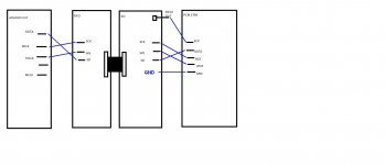
The MCLK and GRD out of Amanero is not connected ?
Ground must be connected. Mclk is not connected.
- Home
- Source & Line
- Digital Line Level
- Asynchronous I2S FIFO project, an ultimate weapon to fight the jitter