Greetings,
I got my batteries from DVB-projekt's contact.
Does anyone have a schematic for a batery management for them?
will Ian's pcb work well with these?
regards.
You could use Ian's pcb without problems!
I use THIS LiFePo4 charger from them with Ian's pcb in between.
")
Ian
tested the i570 with BIII yesterday and the sound is great. thanks for your great work.
As I have the single and dual clock boards, I wonder if I can use those as the clock source for other devices such as CD transport, or even the Amanero reclock?
Hi bigpandahk,
Both single and dual clock board were designed can work independent from the FIFO. They all have DC power input connector. Dual XO clock board can even switch MCLK frequency manually by the push button. Re-Clock function is also available there. Hope you can make good use of them.
Regards,
Ian
Greetings,
I got my batteries from DVB-projekt's contact.
Does anyone have a schematic for a batery management for them?
will Ian's pcb work well with these?
regards.
Hope it helps.
Ian
Attachments
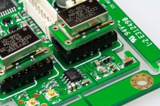
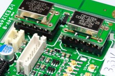
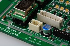
Power the dual XO clock board by 3.2V LiFePO4 battery direct
Some changes have to make to the Dual XO clock board to power it by a LiFePO4 battery cell directly because of the internal LDOs.
Steps (Please see the pictures for details):
1. Remove the two on-board ADP151 3.3V LDOs U7 and U8 from PCB, SMT re-work tool is preferred.
2. Short Pin1 and Pin5 of the footprint of both U7 and U8 by two 0 ohm 1206 chip resistor jumpers.
3. An isolator board must be placed between FIFO and the clock board in your system.
(Without this isolator board, FIFO board could be damaged from the shorting of two power supply)
4. Connecting one LiFePO4 battery cell to the DC input connector J5 on the dual XO clock board via a battery management board.
Some comments:
1. 26650 would be a better choice than the 18650 for selecting the LiFePO4 battery cell.
2. Magnet ring is suggested for the battery cable because of the load frequency could be very high for a clock board.
3. If it is possible, try to monitor the battery voltage by a passive voltage meter to avoid any damage caused by over discharge.
Ian
Attachments
Magnet ring is suggested for the battery cable because of the load frequency could be very high for a clock board.
Hi Ian,
did you have a part no. from Mouser or Digikey for the recommended ring?

MiniDSP & Buffalo
I am using a MiniDSP digital XO for my 3 way system. I am happy with it, but I want to see what a better DAC can do and have a 8 channel Buffalo 3 on my way. I am planning to hook it up to three of the four I2S busses available on the MiniDSP.
However, if I want to use a FIFO KIT, I assume the logical approach is to feed the MiniDSP with the I2S stream from the FIFO KIT and set up both the MiniDSP and Buffalo3 DAC to use the clock from the FIFO KIT? Am I correct?
If that is an option I am up for GBV.
the miniDSP will not take full advantage of the fifo, especially the last gen boards. the miniDSP resamples everything to 48 or 96kHz (so to get any use out of the fifo at all, you would need to resample all of your library to 48 or 96khz beforehand), it has a fairly noisy power supply, lacks impedance controlled i2s inputs and outputs and its DSP adds enough jitter to make the input jitter fairly insignificant within reason.
myself I would wait till Ian finishes the multichannel fifo and put the fifo between the miniDSP and BIII.
I have been considering getting the miniSHARC and resampling all my music to 48 or 96khz and designing a board to properly interface the fifo to miniSHARC, but I do think the advantages are few. its hard to know exactly the amount of jitter the DSP adds, but going by other similar devices it wont be insignificant.
Last edited:

If it is possible, try to monitor the battery voltage by a passive voltage meter to avoid any damage caused by over discharge.
I found a small and cool looking voltmeter HERE.
Great to integrate in a front panel.
What do you think...
Attachments
Hi Ian
while still trying hard to understand your i570 protocol for the Arduino code, I am trying to verify the communication port of the i570 is working. I connected it to the RS232 port of my PC and use hyper-terminal to monitor its output but see nothing.
Could you advise the comment in ASCII for requesting the sampling frequency?
I found a small and cool looking voltmeter HERE.
Great to integrate in a front panel.
What do you think...
not passive and fullscale is 200mV, so you will need to add something to accurately attenuate the voltage to feed to it. looks cool though ...
my god its expensive!
Last edited:
Hi Ian
while still trying hard to understand your i570 protocol for the Arduino code, I am trying to verify the communication port of the i570 is working. I connected it to the RS232 port of my PC and use hyper-terminal to monitor its output but see nothing.
Could you advise the comment in ASCII for requesting the sampling frequency?
The protocol doesnt allow that.
The protocol send event data whenever the fifo has a change.
Change the fifo input while you read the serial port, compare what you receive with the information Ian has given. I don't think it is fair for Ian to be answering these questions.
When I connect the Arduino to the i570, the i570 doesn't select the correct clock for the BIII. Normally, the three LEDs for Fs shall be on when playing music. With the Arduino connected, only the 512 is ON. No lock on BIII.
If I connect it to the PC RS232 port, it keep on sending some data and all the LED for the MCLK flashing. Also no lock.
Thanks for your advise, I will try some other method to see if I can solve the problem.
If I connect it to the PC RS232 port, it keep on sending some data and all the LED for the MCLK flashing. Also no lock.
Thanks for your advise, I will try some other method to see if I can solve the problem.
Hi Ian
I am trying to read the sampling frequency from i570 and display it on GLCD. Is there any simple instruction to do it? I don't understand how to use your code.
Hi bigpandahk,
I would suggest you first trying to program your controller to listen to the message sent from Si570 clock board.
Once you get to know what it’s talking about, it will be very easy for you to figure out how to display and control it.
The protocol I gave was originally from Si570 driver source code, you can use them directly in your C/C++ code by removing the “//”
Ian
I found a small and cool looking voltmeter HERE.
Great to integrate in a front panel.
What do you think...
Yes, it looks cool
. With a couple of hundreds K resistors and internal battery/power supply, I don't think it will introduce anything.Ian
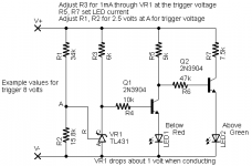
Simple Above/Below voltage monitor:
That's another nice solution. Very easy to implement. All components a passive, it's worth to give a try.
Ian
Hi bigpandahk,
I would suggest you first trying to program your controller to listen to the message sent from Si570 clock board.
Once you get to know what it’s talking about, it will be very easy for you to figure out how to display and control it.
The protocol I gave was originally from Si570 driver source code, you can use them directly in your C/C++ code by removing the “//”
Ian
Thanks Ian
That's what I've done. Will learn more from the WEB and try.
- Home
- Source & Line
- Digital Line Level
- Asynchronous I2S FIFO project, an ultimate weapon to fight the jitter