Ray, its misleading to say you can realistically input +36v for a +1.4v output and you have not even covered load current. this application of the TPS reg does not have much copper for heatsink, its designed for a low dropout voltage at 100-150ma in this application. the TPS gets best performance with ~1V dropout to work with.
As you previously have written -> It is in the data sheet
a cap multiplier will negate or complicate the use of the load sense function, load regulation and transient response suffers, so not sure of the improvement
If you check the previous posts you may realize that I wrote "in front of the regulator" and not "after".
Ray thank you, at least somebody understands my questions! At times it seems we are talking different languages here! : )
That was the information I've been looking for, it didn't cross my mind I could look up this info in the data sheet. For some reason been carrying the impression around this is such a highly integrated circuit, that only the creator of it could answer me.
qusp, I've been reading the thread and associated ones back and fort, must have missed it, if it is there. You kind of interpret a bit more into my questions than necessary - for sure this was not a debate about batteries!
bkdog, ya, I was surprised by the improvement too, give it a try!
My questions were about Ian's regulators, I've only brought up the tridents, because Ian has them too, so it might be easier having a common ground.
Thank you guys ...
not reallyyes, everyone DOES have trouble, measuring 1ps phase noise is troublesome, no matter what equipment you have.
")
Nazar,
we have a bit to learn.
Well, let me know the difference measuring a standard XO like the Crystek and a state of the art OCXO like the HCD.
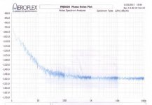
Take a look at the attached image, maybe is easier measuring the state of the art device, since 1 Hz offset from the carrier is showed? Or simply Crystek choice to not display the result at 1 Hz offset? At the bottom of the phase noise analisys you can read: Start 10Hz. But such kind of Agilent measures below 1 Hz.
Well, now let me know the difference starting at 1 Hz or 10 Hz with an Agilent E50 or E55 series or an Aeroflex PN9000.
I'm very curious.
P.S. An useful link to convert phase noise into RMS jitter
http://www.raltron.com/cust/tools/osc2.asp
we have a bit to learn.
Well, let me know the difference measuring a standard XO like the Crystek and a state of the art OCXO like the HCD.
Take a look at the attached image, maybe is easier measuring the state of the art device, since 1 Hz offset from the carrier is showed? Or simply Crystek choice to not display the result at 1 Hz offset? At the bottom of the phase noise analisys you can read: Start 10Hz. But such kind of Agilent measures below 1 Hz.
Well, now let me know the difference starting at 1 Hz or 10 Hz with an Agilent E50 or E55 series or an Aeroflex PN9000.
I'm very curious.
P.S. An useful link to convert phase noise into RMS jitter
http://www.raltron.com/cust/tools/osc2.asp
Attachments
Last edited:
not really
yet more contextual issues, but of course we know that your abilities dwarf that of those that do this sort of thing every day for work. you know, I almost made a recording with a date on it predicting that you, or some other person who likes to present as some sort of super human would say its easy. so I could play it back to show how predictable you guys are.
As you previously have written -> It is in the data sheet
If you check the previous posts you may realize that I wrote "in front of the regulator" and not "after".
no Ray not as you have understood it, I guess you havent worked with LDOs very much, especially with packages like this. with this area of copper, ie less than 2 square inches, we have best case ~50 degrees C/W temperature rise above ambient with 2oz copper (not sure if its 2oz or 1oz copper on this board) and the part thermally limits at 170c... just how much current do you think you could drive through this reg with a 34.6v voltage drop with that in mind?
PD = (Vin-Vout) x Load current
PD = (36v - 1.4v) x 125mA
PD = 34.6 x 125mA
PD = 4.325W
ambient 20c leaves 150c rise, at 50c/w thats about 3W if its 2oz and if its a perfect and direct connection between the die and the heatsink, which it isnt, for reliable operation its recommended to keep it at 125c, so 2W
so even without taking the interface from the package to the heatsink into account we have more than doubled the recommended current limit.
it may allow 36V input with 1.4v output, but its not a miracle reg, it still must obey thermo-dynamics
depending on the output caps, I wonder if it would even start under such conditions.
Last edited:
no Ray not as you have understood it, I guess you havent worked with LDOs very much, especially with packages like this. with this area of copper, ie less than 2 square inches, we have best case ~50 degrees C/W temperature rise above ambient with 2oz copper (not sure if its 2oz or 1oz copper on this board) and the part thermally limits at 170c... just how much current do you think you could drive through this reg with a 34.6v voltage drop with that in mind?
PD = (Vin-Vout) x Load current
PD = (36v - 1.4v) x 125mA
PD = 34.6 x 125mA
PD = 4.325W
ambient 20c leaves 150c rise, at 50c/w thats about 3W if its 2oz and if its a perfect and direct connection between the die and the heatsink, which it isnt, for reliable operation its recommended to keep it at 125c, so 2W
so even without taking the interface from the package to the heatsink into account we have more than doubled the recommended current limit.
it may allow 36V input with 1.4v output, but its not a miracle reg, it still must obey thermo-dynamics
depending on the output caps, I wonder if it would even start under such conditions.
I use the TPS7A47 LDO voltage regulator - configured optimal for my designs.
I do not know what your intentions are, but I leave you to them alone.
hehe I dont care if you use it or not, you are bound by the same issues as with this design, to the thermal performance of the PCB as well as dropout and load current, you do not have a trick to avoid this. with that kind of dropout, you might squeeze 30-40mA max before it limits or ceases to give you anywhere near the stated performance.
do not give advice like that without considering the actual situation. larger copper area may mitigate, but not avoid the issue and remember this is a 1A device, its not even possible to make a PCB that will get 1A output with that much dropout.
do not give advice like that without considering the actual situation. larger copper area may mitigate, but not avoid the issue and remember this is a 1A device, its not even possible to make a PCB that will get 1A output with that much dropout.
Last edited:
Just when someone said something wrong it would be easy to step back.
Keep in mind, I know the answer, HCD build the OCXO as a custom part for me, so I know how many time they spent to trace the phase noise...
again, if was not clear... WITH THE PROPER EQUIPMENT.
if I wasnt clear, even with the proper equipment, it still isnt a simple or quick issue. ask them how long it took them and how much their test fixture cost them where you bought the XO's. good chance they built and characterized a buffer and its performance is deducted from the measurement
You have to read more carefully, as I said I know how many time they spent to measure the OCXO, and I don't tell you, since seems you already know that.
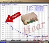
Maybe you don't know these are automatic phase noise measurement system, with built-in ultra low phase noise reference OCXO, ultra low noise preamplifier and a PLL to tune the exact frequency under test. The spectrum analyzer display the result, automatically. Just tuning the PLL.
The cost of such that equipment can vary from 20.000 USD up to 100.000 USD or more. But this is out of context, since I said several times "with the proper equipment" and I never said there is a cheap way to do that.
But seems you have no intention to step back, so I give up.
right, OK so you make a completely useless suggestion that has no relevance to anyone at all apart from a company making XO's
I gather they now make space probes to go to the other planets also, do you think you could tell us what the soil is like? I have always wondered and i'm writing a thesus. I have a pretty good idea based on data I have read elsewhere, but I would really like to know for myself. I dont have the money for the probe though, I figure with enough money and time you could make it happen. you remember me, I bought your car last year...
obviously i'm exaggerating
even with that I doubt very much its like operating an easybake ovenask them how long it took them and how much their test fixture cost them where you bought the XO's.
I gather they now make space probes to go to the other planets also, do you think you could tell us what the soil is like? I have always wondered and i'm writing a thesus. I have a pretty good idea based on data I have read elsewhere, but I would really like to know for myself. I dont have the money for the probe though, I figure with enough money and time you could make it happen. you remember me, I bought your car last year...
obviously i'm exaggerating
Last edited:
Does anyone have a link to the GBII fifo instructions?
Here:
http://www.diyaudio.com/forums/group-buys/207438-ian-asynchronous-i2s-s-pdif-fifo-kit-group-buy-40.html#post3093337
Hope it helps
.Ray, its misleading to say you can realistically input +36v for a +1.4v output and you have not even covered load current. this application of the TPS reg does not have much copper for heatsink, its designed for a low dropout voltage at 100-150ma in this application. the TPS gets best performance with ~1V dropout to work with.
a cap multiplier will negate or complicate the use of the load sense function, load regulation and transient response suffers, so not sure of the improvement
the question was directly feeding the board with batteries, or regulate beforehand, therefore the dropout of the onboard regs was the dropout under discussion, not the dropout for the TPS7A4700
Yes, actually TPS7A4700 has some sweet input ranges. I could be wrong, base on my test, for a 3.3V output, it's 4V-5V.
Hope can do more research and test.
Ian
You have to read more carefully, as I said I know how many time they spent to measure the OCXO, and I don't tell you, since seems you already know that.
Andrea:
I'm interested in finding out more about these oscillators. The info seems to be spread among several threads. Can you provide details or a link to a source? I have quotes for some really serious oscillators but they are really expensive and have a long lead time. If you have a source or circuitry that can get to the same place as the published plot I'm all ears.
- Home
- Source & Line
- Digital Line Level
- Asynchronous I2S FIFO project, an ultimate weapon to fight the jitter