I have a WaveIO USB. But I’m not happy with the 2.5ns jitter problem on I2S output caused by XMOS, though it’s no longer an issue working with my FIFO.
Have you measured the "2.5ns jitter" by yourself? Have your FIFO completely eliminated the sound degradation caused by the jitter?
I think the 2.5ns is four times better than the minimum time tick that ES9018 has with 100MHz asynchronous MCLK.
Have you measured the "2.5ns jitter" by yourself?
YES
Have your FIFO completely eliminated the sound degradation caused by the jitter?
For the jitter caused by XMOS, I think so, but try it by yourself if it is possible
")
I think the 2.5ns is four times better than the minimum time tick that ES9018 has with 100MHz asynchronous MCLK.
Do you mean ESS9018 does not care about the 2500ps jitter from the SCK/BCK, WS/LRCK?
Regards,
Ian
It's amazing! You must be the only person who measured actual and accurate jitters in this community. How respectful!
By the way, what RMS value did you obtain in which frequency range? I think 2.5ns is the maximum value and the density distribution between zero and 2.5ns would be uniform. The RMS value is supposed to be get small.
For the jitter caused by XMOS, I think so, but try it by yourself if it is possible
Sorry. My current interest is only on plays of DSD256/512 sources.
Do you mean ESS9018 does not care about the 2500ps jitter from the SCK/BCK, WS/LRCK?
My speculation is like this;
ES9018 architecture can not generate any shorter timing event than MCLK interval. Their "jitter reduction" functionality is not a fine adjustment along time axis but an interpolation of sound intensity values.
I only apply a synchronous master clocking scheme to the DAC chip. In this case, we can make the timing gap to zero.
By the way, are you engaged in development of FDA regulated medical devices?
I am working with a regulatory agency in Japan. I respect your design style very much.
I can see there are two reasons:
1, Most of the USB isolators we can touch currently are for USB2.0 full speed 12MHz, not for high speed which is 480MHz. In this case, it will degrade the performance of many good USB audio interfaces which were designed optimizing for 480Mhz high speed, especially for higher Fs application as 192KHz and 384Khz.
2, Even when high speed USB isolator becomes popular down the road, I2S/DSD will still be the better solution than the USB isolator. The reason is very clear. Since we have to power the isolated section from DAC side, powering half I2S/DSD isolator comes with much less noise than powering a whole USB interface. The USB interface usually needs a couple of clocks with different frequency running at same time, not only drawing more current, but also introducing much more EMI noise from power supply and ground.
Ian
The other advatage I see most is we are isolating the Fifo's 600MHZ "computer" by this method. If we were to isolate at the USB side little would be gained.
On another subject that I've been running into, would there be any possibilty to offer that HDMI LVDS I2S output. I know its not technically the best but it just seems to be something worth offering, I know this has been discussed before and several arguments were made against it but is there any chance of revisting that discussion ? I do see an advantage in a balanced i2s as far as rfi and ground loops. What are the disadvantages?
The other advatage I see most is we are isolating the Fifo's 600MHZ "computer" by this method. If we were to isolate at the USB side little would be gained.
I agree that Ian's bi-directional FIFO isolator board is excellent. But I think you've missed the design they're talking about here as 'this method'. They are currently referring to Ian's new generic isolator for use between transport device and the FIFO input. Ian's design posted here - http://www.diyaudio.com/forums/digi...mate-weapon-fight-jitter-213.html#post3329364 It's been buried quickly in a couple of pages of posts so you probably missed it by not quite reading far enough back, easy to do in a fast moving thread!!
I have no opinion on HDMI LVDS I2S at this stage so I'm not ignoring your question, just don't know enough about it to give a meaningful/useful opinion.
It's amazing! You must be the only person who measured actual and accurate jitters in this community. How respectful!
By the way, what RMS value did you obtain in which frequency range? I think 2.5ns is the maximum value and the density distribution between zero and 2.5ns would be uniform. The RMS value is supposed to be get small.
...
Hi Bunpei,
There were other measurements done by fetaudio.com a while back. (not to take any credit away from Ian -who in addition has made the only measurement I know of the 8805 aside from the manufacturer)
Seemed on the high side at the time, since one can expect "hundreds of psec" p-p, but the Xmos device has been well received by the audio community so didn't think too much about it.
This 2.5 nsec RMS comes as a surprise.
It's amazing! You must be the only person who measured actual and accurate jitters in this community. How respectful!
By the way, what RMS value did you obtain in which frequency range? I think 2.5ns is the maximum value and the density distribution between zero and 2.5ns would be uniform. The RMS value is supposed to be get small.
Yes, I'm not the fist one found this problem. Actually I didn't notice it at beginning because I use it as fifo input and the 2.5ns jitter was just within sweet range, I didn't feel anything wrong. After I post the pictures of WaveIO and FIFO, a guy asked me if I noticed the jitter issue, he did some test on his scope but he was not quite sure. I didn't believe that until I google "XMOS 2.5ns jitter problem". I was quite surprised. So, I did some measurement, unfortunately it was approved true. Actually the jitter histogram has two peak with 2.5ns time interval in between. Not the normal concept Gaussian jitter which is caused by the quality of XO. Obviously it's kind of determined system jitter caused by the processor. But I wouldn't post result of the screen shot, it's not fair. WaveIO is a very good design with nice layout and has nothing to do with this problem. It's totally the XMOS problem.
Sorry. My current interest is only on plays of DSD256/512 sources.
My speculation is like this;
ES9018 architecture can not generate any shorter timing event than MCLK interval. Their "jitter reduction" functionality is not a fine adjustment along time axis but an interpolation of sound intensity values.
I only apply a synchronous master clocking scheme to the DAC chip. In this case, we can make the timing gap to zero.
By the way, are you engaged in development of FDA regulated medical devices?
I am working with a regulatory agency in Japan. I respect your design style very much.
Glad you like my design. They are medical grade
.Good to know you work for FDA agency. Yes, we are involved in FDA registration each time when we release a new product. As well as CE. From next week, I'll work for two weeks with a local testing labs for the EMI,EMC and safety test on another new release. Just cross your fingers
Have a nice weekend.
Ian
Last edited:
I have a WaveIO USB. But I’m not happy with the 2.5ns jitter problem on I2S output caused by XMOS, though it’s no longer an issue working with my FIFO.
That 2.5ns problem has got to make you wonder why TPA are spending a few years developing their own XMOS based design usb adapter
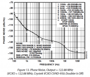
AD9525 total overkill ???
Some numbers are impressive but -89dbc/hz at 100hz is not the best we have seen.
Attachments
Last edited:
Some numbers are impressive but -89dbc/hz at 100hz is not the best we have seen.
Yes I agree, but a lot better to hear the noise in the higher audio band where its will be more pronounced. I would rather have it where its nearly inaudible rather than in the 8K - 20K range....
That 2.5ns problem has got to make you wonder why TPA are spending a few years developing their own XMOS based design usb adapter
I am curious to know why you and others are referring to the 2.5ns jitter of the XMOS chip (could be any other chip as well) as a "problem".
Do you believe that the proper and/or unique point for perfect timing accuracy should be at the chip that "translates" USB data to I2S signals?
Why to try to be perfect in timings close to the source? Should we go back to the synchronous USB transports as well?
If you use a very simple I2S re-clocking circuit, similar to the ones found here, don't you get excellent results?
(Of course there are some limits of the amount of jitter that can be compensated, but I believe 2.5ns is orders of magnitude lower).
I think that many times there are exaggerated comments about the performance of some components without the proper justification.
Many functions may be performed in various points of a telecommunication chain/system (and audio reproduction may be considered as one).
Fortunately the contemporary digital systems provide excellent mechanisms that assist the design of a system that has not to be perfectly synchronous from the one end to the other.
Ian's design proves that there are ways to connect two different clock domains and get perfect results, with the only constraint of the buffer size.
But if you use the same clock for both the USB to I2S conversion system and the DAC, one very simple re-clocking system is enough (no buffer is needed).
The DAC will get all the bits jitter-free and you can have the clock(s) and re-clocking mechanisms really close to the DAC where is more important.
"Problems" like this should be the boost for better circuit designs that may not be simpler, but may provide better results than the "simplistic" ones.
..subscribed.. exactly what I said some posts ago.But if you use the same clock for both the USB to I2S conversion system and the DAC, one very simple re-clocking system is enough (no buffer is needed).
The DAC will get all the bits jitter-free and you can have the clock(s) and re-clocking mechanisms really close to the DAC where is more important.
The asynchronous way (the FIFO buffer) is the right option if you cannot synchronized the DAC with the source (USB to I2S conversion or any other source).
Anyway, IMHO, the DAC (BCLK) should be feeded directly from the MCLK, as close as possible to the DAC chip. also if you are using an asynchronous re-clock like the FIFO buffer.
Ian
When I connected an optical source to the SPDIF, it has lock LED on but no sound at the BIII, both Mute and Lock LEDs on BIII on, the system works perfectly with WaveIO connected to the I2S backdoor. Please HELP.
Ian
Same problem on the coaxial input, so only the I2S backdoor is working.
- Home
- Source & Line
- Digital Line Level
- Asynchronous I2S FIFO project, an ultimate weapon to fight the jitter