No, at least there are another two, the ExaU2I (ExaU2I) and the above mentioned exD (exD) but at $399 they are 10x the price and the former, in its current version, can only play DSD through a propietary app though it does MCh.
BTW, it is possible to rip native DSD files (ISO, DFF or DSF) in either stereo or MCh from any SACD disc using one of the older PS3s. Some infosacd-ripper:
BTW, it is possible to rip native DSD files (ISO, DFF or DSF) in either stereo or MCh from any SACD disc using one of the older PS3s. Some infosacd-ripper:
Last edited:
I've used all three, and they each have their strengths. The eXD and the ExaU2I sound better in stock form (and of course, the exaU2I doesn't do DSD apart from some monkey business). I'd be very pleased if with using a PS instead of USB power the Combo384 performs at a similar level as the other two.
Click on the 'exD' in post #1422 above. Separate board. Overall, very well done. Good onboard regulation, accepts 6V PS, separate headers for I2S and DSD (they can flash the firmware to multiplex I2S/DSD for the ESS chips that support both).
I've been using one of these with FIFO; OttoII handling the switching duties. Very nice.
I've been using one of these with FIFO; OttoII handling the switching duties. Very nice.
I'm waiting for the TPS7A4700 PCB to test my Si570 clock board. Hopefully I can get them this week.
Si570 driver firmware programming job are almost finished with partly opening the frequency control function to the third party external controller.
Isolator board also reserved an isolator footprint for the external controller, as well as an isolated I2C port for the DAC (ESS9018).
Ian
Si570 driver firmware programming job are almost finished with partly opening the frequency control function to the third party external controller.
Isolator board also reserved an isolator footprint for the external controller, as well as an isolated I2C port for the DAC (ESS9018).
Ian
Is that Amanero the only USB capable for native DSD output so far?
In Japan ElectrArt's "USB Dual Audio" board is very popular among local DIY users.
http://www.diyaudio.com/forums/digital-source/177336-usb-dsd-dac-adc-electrart-2.html#post3114795
The board supports DSD64, DSD128 and DSD256 of both 44.1kHz & 48 kHz series.
Moreover, he is preparing PCM to DSD256 or DSD512 converter hardware board.
http://www.diyaudio.com/forums/digital-source/177336-usb-dsd-dac-adc-electrart-4.html#post3217924
Si570 interest list:
1. bigpandahk
2. tagheuer
3. hochopeper
4. qusp (of course)
5. AR2 - definitely!
6. wktk_smile
7. hirez69
8. CeeVee - you bet!
9. number9
10. analog_sa - GB maniac
11. edbk
12. atom6422
13. misterrogers - Of Course!
14. NicMac - as usual!
15. Zoran 16. PET-240
17. Coolhead
18. Slartibartfasst
19. SYklab
20. Regland
21. Neb001
22. SPWONG
23. Greg Stewart (also of course!)
24. Vitalica
25. spm
26. Fridrik
27. ccliu
28. makumba1966
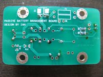
Battery management board test 1
Last night did a brief test with it. 3 scenarios:
1. Default power supply from FIFO board (6v)
2. Power by salas bib shunt regulator tune to 180mA ccs, 6v
3. With the power management board, 4x rechargeable NiMh Sanyo AA battery 2000mA, 5.6v fully charge.
I don't have tool to measure, only depends on my ear. I think 2 is the better by a hair to 3. With separate power supply, it is more refine, smooth and bass in better.
My configuration is simple Sony 338esd -> coax -> FIFO -> coax -> BII -> tube I/V -> amp.
I have a phone LiPo battery, i am thinking of removing U7 on the clock board and direct feed the power there. But the battery is 3.6v, can it be use?
Thanks.
Fully charge is about 4v without load. With phone turn on is about 3.7v, will drop to 3.5 when depleted.is it really 3.6 when fully charged?
Ian,
I connected LEDs and switch from the S/PDIF board via 10 pin connector on the board. It works, but it is extremely dimmed. Is there anything that can be done to make them brighter. LEDs I am using on the front panel are regular green ones. Would it help if I remove LEDs from the board? I will not be using those, and if the signal is just paralleled to those it might double the output?
Next - when unit is turned on it always go by default to Optical input. Is there any chance of changing the default setting to some other setting?
Also you did not use digital transformer for coax S/PDIF input? Since I removed coax and optical input from the board and installed them on the case (I run coax cable 75 ohms between the connector and board) should I install digital transformer, or you prefer not to use it?
Thank you
AR2
Ian,
I connected LEDs and switch from the S/PDIF board via 10 pin connector on the board. It works, but it is extremely dimmed. Is there anything that can be done to make them brighter. LEDs I am using on the front panel are regular green ones. Would it help if I remove LEDs from the board? I will not be using those, and if the signal is just paralleled to those it might double the output?
Next - when unit is turned on it always go by default to Optical input. Is there any chance of changing the default setting to some other setting?
Also you did not use digital transformer for coax S/PDIF input? Since I removed coax and optical input from the board and installed them on the case (I run coax cable 75 ohms between the connector and board) should I install digital transformer, or you prefer not to use it?
Thank you
AR2
Hi AR2,
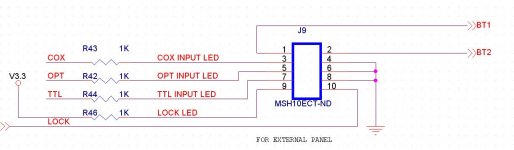
1, Each panel LED have independent current limitation resistor which has no business with the on-board LED. They are R42, R43, R44 and R46. Now, all of them are 1K. Reducing the resistance of them will increase the panel LED brightness. You don't need to remove them from the board, just stack another 0603 chip resistor on top of the old one making them in parallel. I attached the schematic of this part just for reference.
2, The S/PDIF source selection was controlled by hardware not the software, so remember the default setting for next power up would be very hard to achieve in this case. You have to manually select the s/pdif source, or somebody else could provide a third party controller with the simulation of key pressing.
3, Almost all coaxial s/pdif source has output transformer, and also, with FIFO included in system, we don’t care much about the input jitter from s/pdif source, so I don’t think we need the input transformer for the s/pdif board.
For the USB based s/pdif sources, I always prefer the optical s/pdif for better galvanic isolation. With FIFO, there is no difference on sound between optical and coaxial. I did big loop test via both input and output optical port at 192Khz for more than 2 hours with bit-perfect result.
But if you really want, you can place a digital transformer between the RCA/BNC socket and the s/pdif board. DIX9211 has RF amp inside, so no worry about the level. Please see the DIX9211 pdf file for details. http://www.ti.com/lit/ds/symlink/dix9211.pdf
Have nice weekend
Ian
Attachments
Ian
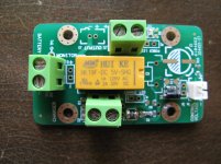
Assembled the battery management board and is functioning, but I use the wrong type of relay. The output is connected to the charger instead of battey when J8 shorted
You need DPDT (2 Form C) relay. Three options on the footprint. Higher rated current would be better.
1. G2RL-2 DC5, Z3087-ND
2. TX2-5V, 255-1031-5-ND
3. G2R-2-DC5, G2R-2-DC5-ND
4. 8-1393792-5, PB383-ND
You don't need R5 and R6, they must keep NC for the standard configuration except you want to control the relay from the charger. Please see the picture below.
Standard configuration
J8: Control voltage input
J1 or J2: Charger input
J11 or J12: Battery input
J3 and J5 or J7: Output
K1 or K2 or K3: Relay
D4: IN4148
F1: MICROSMD110F-2 or just short
R1, R8 and R10: 0 ohm 0805 or just short
R7: 1K 0603
D3: LED 0603
Ian
Attachments
Last edited:
You need DPDT (2 Form C) relay. Three options on the footprint. Higher rated current would be better.
1. G2RL-2 DC5, Z3087-ND
2. TX2-5V, 255-1031-5-ND
3. G2R-2-DC5, G2R-2-DC5-ND
4. 8-1393792-5, PB383-ND
You don't need R5 and R6, they must keep NC for the standard configuration except you want to control the relay from the charger. Please see the picture below.
Standard configuration
J8: Control voltage input
J1 or J2: Charger input
J11 or J12: Battery input
J3 and J5 or J7: Output
K1 or K2 or K3: Relay
D4: IN4148
F1: MICROSMD110F-2 or just short
R1, R8 and R10: 0 ohm 0805 or just short
R7: 1K 0603
D3: LED 0603
Ian
R5 and R6 is just for testing, I will remove them and put R10.
Thanks
bigpandahk, make sure to populate the fuse.... =)
Sure, thanks for reminding me
- Home
- Source & Line
- Digital Line Level
- Asynchronous I2S FIFO project, an ultimate weapon to fight the jitter