Found some from eBay(just found, not for recommendation):
SMD SMT Soldering Rework Station 2in1 Hot Air Gun Iron Welder Tip ESD PLCC BGA | eBay
New 2 in1 SMD SMT Soldering Rework Station Welder Hot Air Iron 852D 220V | eBay
Soldering wires, solder paste and flux are also importatn.
Ian
I am contemplating this one: Kerry D. Wong Blog Archive X-TRONIC 4040 Hot Air Rework/Soldering Station – I
Seems a bestseller on ebay (I suppose you need the 220V version?)
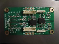
Here is the picture.
Looks good from picture. You need confirm no any short by a multimeter.
Make sure FFC cable on it's correct contact side, the two 10P sockets you bought from Digikey are single side contact. I use double side on dual clock board to avoid this kind of issue.
Another thing I'd remind again is, powering the clock board prior to the FIFO, if you don't have the battery management.
Good luck.
Ian
did you by chance have both the spdif and clock boards connected to the same arduino? half asleep now, off to bed, that would probably just circumvent the isolation, rather than anything dangerous... boards look OK from a glance
obviously something wasnt right though....
obviously something wasnt right though....
Last edited:
Hi glt,
I use Potato logic FFs on the 570 clock board. The Tpd=2ns. So, all of the I2S signals will be delayed 2ns after raising edge of MCLK. If feed reversed MCLK into ESS9018, take 98.xxx Mhz, the I2S delay will be 5.1+2=7.2ns, that's the only difference. Using slower HC FFs will get the same thing.
Is there any details about reversing 9018 MCLK?
Nice weekend.
Ian
According to this app note: http://esstech.com/PDF/Application_Note_Component_Selection_and_PCB_Layout.pdf on page 5:
"If operating with a synchronous MCLK, it is recommended to use an inverted MCLK. The inverted synchronous MCLK ensures that the Sabre noise is as low as possible."
According to this app note: http://esstech.com/PDF/Application_Note_Component_Selection_and_PCB_Layout.pdf on page 5:
"If operating with a synchronous MCLK, it is recommended to use an inverted MCLK. The inverted synchronous MCLK ensures that the Sabre noise is as low as possible."
Thanks glt, that's an interesting story. For an sync I2S input, that means it potimized to signals synchronized with the falling edge of the MCLK.
Unfortunately the CMOS version of Si570 doesn't have a inverted output. However it could still be achieved by replace the potato 74G74 with 74AC74 to get same amount of timing relationship for the 98.xxx and 95.xxx MCLK. Will give a try to see if there is any audible difference.
Ian
Last edited:
Power the isolator board by bench PSU and both sides draw 80mA at 5.5V and seems fine. Will check the signal path later.
Think about the incident last night, the L11 burnt when I was fixing the bad contact problem with the battery. The LED on the clock board flash couple of times and fire started on L11. May be the transient overloaded the L11.
Think about the incident last night, the L11 burnt when I was fixing the bad contact problem with the battery. The LED on the clock board flash couple of times and fire started on L11. May be the transient overloaded the L11.
Attachments
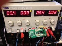
wow those regs arent as efficient as I thought, the isolator itself should only be drawing about 10ma a side maximum, especially with the inputs and outputs unloaded. or you mean thats where you have the current limit set? if there is now no problem with the iso board, its very doubtful just a transient did that as there simply isnt that much current draw or capacitance/inrush under normal operating conditions, you must have shorted or reversed the battery somehow.
Last edited:
wow those regs arent as efficient as I thought, the isolator itself should only be drawing about 10ma a side maximum, especially with the inputs and outputs unloaded. or you mean thats where you have the current limit set? if there is now no problem with the iso board, its very doubtful just a transient did that as there simply isnt that much current draw or capacitance/inrush under normal operating conditions, you must have shorted or reversed the battery somehow.
The displays showed the current load not limit set. After confirmed no short on the isolator, I put it back to the circuit. Found that no signal at two outputs that provide clock to FIFO. That may explain why SPDIF not function. Replace the IL260 with i8650, SPDIF function again. But I2S still have problem. Replace the second IL260 with i8650. SPDIF not working again
To avoid making further mistake, I should take a rest and plan the step for trouble shooting. May be my skill is too poor for DIY
Did you confirm no any short of disconnection. Since you have the schematic, doing this job would be easy. Than I suggest doing the high-low test to each channel by jumping the input to GND or vdd to confirm they all working.
I don't thinks 80mA on each side is correct, will check up it on my IL260 board.
--------------
Just conform my IL260E isolator board consumes only 5.2mA on FIFO side (6V input, without signal connected), so please test the current again after remove all isolator and confirm you LDO is working correctly.
Ian
Last edited:
Did you confirm no any short of disconnection. Since you have the schematic, doing this job would be easy. Than I suggest doing the high-low test to each channel by jumping the input to GND or vdd to confirm they all working.
I don't thinks 80mA on each side is correct, will check up it on my IL260 board.
--------------
Just conform my IL260E isolator board consumes only 5.2mA on FIFO side (6V input, without signal connected), so please test the current again after remove all isolator and confirm you LDO is working correctly.
Ian
yep thats more what I was predicting based on the datasheet, seems like something is causing short circuit on both sides for both fifo and clock side to be drawing the same 80ma.... strange, but it could be the resistor network on both sides perhaps?
Bigpandahk, I would suggest that you check your 4 resistors network wich soldering could shorten to ground Input and /or Output Signals.
Only the following resistors of the network are connected to Gnd :
R1 : 2nd and 4 th resistors
R2 : 2nd resistor
R3 : 1st and 3rd resistors
R4 : 2nd and 4th resistors
First resistor of every network is the one that is the nearest to the inscription "digital isolator board"
If you find with your multimeter any grounded resistor which is not listed hereabove it means that there are some soldering shortning on the resistor networks
Yes, the main problem is related to the resistor arrays. I remove all 4 arrays and check the current again. both sides reduced to less than 5mA. I replaced all 4 arrays and everything seems fine. The resistance to ground raised above 500K. But when I connected it to the clock and FIFO for couple of minutes, the resistance dropped to less than 100K again.
I may need to find a better way to solder the arrays. But anyway there is progress.
Thank you for ALL of YOU.
I may need to find a better way to solder the arrays. But anyway there is progress.
Thank you for ALL of YOU.
Yes, the main problem is related to the resistor arrays. I remove all 4 arrays and check the current again. both sides reduced to less than 5mA. I replaced all 4 arrays and everything seems fine. The resistance to ground raised above 500K. But when I connected it to the clock and FIFO for couple of minutes, the resistance dropped to less than 100K again.
I may need to find a better way to solder the arrays. But anyway there is progress.
Thank you for ALL of YOU.
Since i am pretty sure soldering the resistor packs is beyond my skills, I was thinking of using discrete resistors (e.g. 1/8 watt) and solder them to the pads of the isolator. There are only 5 total per isolator
Perfect! certainly a level of contact/influence I cant emulate; lucky you man, wish I could be there....
do you have a novelty food-stuff preparation implement you bring with you also?
No I do not have anything for this year. As for the food stuff, ZenMod is not coming this year, so they will miss his skills, hahaha. As for the electronics, I typically get some standard stuff that everyone can use like tube preamp, CD player, amp... in addition to power cords, blankets, posters, and similar. This year is my first year that I am not involved in organizing it, I pretty much left it to Marc, who is doing really great job on his own. After I closed my studio and started working for company I am with right now, there is really not much time left for hobby.
Another....
Si570 interest list:
1. bigpandahk
2. tagheuer
3. hochopeper
4. qusp (of course)
5. AR2 - definitely!
6. wktk_smile
7. hirez69
8. CeeVee - you bet!
9. number9
10. analog_sa - GB maniac
11. edbk
12. atom6422
13. misterrogers - Of Course!
14. NicMac - as usual!
15. Zoran
16. PET-240
17. Coolhead
18. Slartibartfasst
19. SYklab
20. Regland
21. Neb001
22. SPWONG
23. Greg Stewart (also of course!)
Last edited:
Since i am pretty sure soldering the resistor packs is beyond my skills, I was thinking of using discrete resistors (e.g. 1/8 watt) and solder them to the pads of the isolator. There are only 5 total per isolator
Guys, I have not seen the position and size of those resistor arrays, but what you might find helpful is if you cannot solder the regular way, what sometimes works is to apply solder paste to the pads (very thin layer) and than heat up with hot air, while you are holding resistor pressed from above. If you do not have SMD workstation, you could use heat gun, if it is the one with temperature adjustment. Obviously SMD station will be better, but if you do not have it, heat gun will do the job. You have to be careful not to apply too much of the paste, so the trick is to apply paste and takeaway with cotton swab. What is left is quite enough.
- Home
- Source & Line
- Digital Line Level
- Asynchronous I2S FIFO project, an ultimate weapon to fight the jitter