Wow, thank you so much. Let us know the cost including shipping.
Thanks glt for your kind thought. I posted them in letters, so the shipping were just the postage. Cables are less than a couple of bucks. I don't think you need to pay anything. But if you really want, making some donations down the road to support my R&D would be appreciated
") .
.Regards,
Ian
Passive battery management board
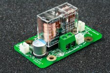
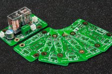
The idea of this passive battery management board is very simple. It’s just a DPDT relayJ. The principle is: Battery is switched to output at working time and switched to charger when the control voltage is gone. There are four groups of connections: battery, output, control voltage and charger. They are all isolated (no any connection) from each other if disconnected (include ground). So, no any EMI noise is expected to be introduced into the output.
Battery type, voltage and charger have no relationship with this battery management board. So, all kind of batteries with corresponding chargers are possible for this small board.
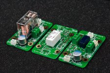
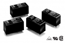
Three kinds of most popular relays with different size are available for this board. Relay selection will be up to how much output current is required.
The battery manage board is not limited to FIFO or clock board application. It’s a universal design and works for any application which needs batteries as power.
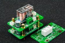
Battery board can be stacked on top of the clock board. Or they may also be stacked over each other to setup a battery management array for multi-group battery applications. In this case, different management board can share a same control voltage, or a high current battery charger if batteries have same voltage from different groups.
System power supply could be used as the control voltage to make all batteries synchronized with it.
Some surrounding components are optional. They can be setup into coil power saving circuit, battery and charger protecting circuit, current limiting resistors for trickle charging, LED indicators, battery monitor and etc.
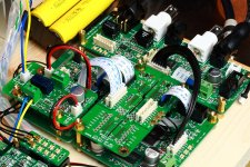
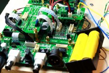
I hooked up this battery management board to my system yesterday. It works very well with my FIFO KIT together with the isolator board. The concept is approved working! I’m just happy with it. I don’t need manually connecting the batteries anymore, as well as picking up them and charging them separately time by time. It works more like a real system rather than a testing projectJ.
Maybe I should post the schematics later on, but I’m sure you already know everything about it from the pictures.
Ian
The idea of this passive battery management board is very simple. It’s just a DPDT relayJ. The principle is: Battery is switched to output at working time and switched to charger when the control voltage is gone. There are four groups of connections: battery, output, control voltage and charger. They are all isolated (no any connection) from each other if disconnected (include ground). So, no any EMI noise is expected to be introduced into the output.
Battery type, voltage and charger have no relationship with this battery management board. So, all kind of batteries with corresponding chargers are possible for this small board.
Three kinds of most popular relays with different size are available for this board. Relay selection will be up to how much output current is required.
The battery manage board is not limited to FIFO or clock board application. It’s a universal design and works for any application which needs batteries as power.
Battery board can be stacked on top of the clock board. Or they may also be stacked over each other to setup a battery management array for multi-group battery applications. In this case, different management board can share a same control voltage, or a high current battery charger if batteries have same voltage from different groups.
System power supply could be used as the control voltage to make all batteries synchronized with it.
Some surrounding components are optional. They can be setup into coil power saving circuit, battery and charger protecting circuit, current limiting resistors for trickle charging, LED indicators, battery monitor and etc.
I hooked up this battery management board to my system yesterday. It works very well with my FIFO KIT together with the isolator board. The concept is approved working! I’m just happy with it. I don’t need manually connecting the batteries anymore, as well as picking up them and charging them separately time by time. It works more like a real system rather than a testing projectJ.
Maybe I should post the schematics later on, but I’m sure you already know everything about it from the pictures.
Ian
Attachments
Last edited:
i'll need the large relay, i've found that in the past even if the supply current doesnt trip/exceed the limitations of the smaller relays, the inrush of small banks of lowZ caps does, so the contacts simply wont open
I am just thinking out loud here, maybe there is value in a soft start for batteries? Maybe 2 relays and initial 5 seconds or so there is a resistor in series before it is switched out.
5A mechanical relay isn't going to last long with 60A+ short circuit from a LiFePO4 battery ...
i'll need the large relay, i've found that in the past even if the supply current doesnt trip/exceed the limitations of the smaller relays, the inrush of small banks of lowZ caps does, so the contacts simply wont open
You can try this one, rated at 8A, pin to pin competable.
G2RL-2 DC5 Z3087-ND
http://www.digikey.ca/product-detail/en/G2RL-2%20DC5/Z3087-ND/1789837
BTW, I like your new logo
) .Ian
Attachments
I am just thinking out loud here, maybe there is value in a soft start for batteries? Maybe 2 relays and initial 5 seconds or so there is a resistor in series before it is switched out.
5A mechanical relay isn't going to last long with 60A+ short circuit from a LiFePO4 battery ...
Soft starting is a very good idea, especially for high current projects such as power amp PUS. Or, maybe a crazy IV stage in some cases
. But that would be another design of high current version.But please do not use soft start for the XO power, because most of digital applications need having clock running prior to other logics
.Ian
Last edited:
Awesome Ian!
When do we start placing orders? HeHe.
iancanada very very great work !!!
Perfect solution, Ian!
Another beauty.
Ed
Thanks guys.
Ian
Soft starting is a very good idea, especially for high current projects such as power amp PUS. Or, maybe a crazy IV stage in some cases
But please do not use soft start for the XO power, because most of digital applications need having clock running prior to other logic
Ian
I was mostly thinking that the soft start would be addressing the high startup current of low impedance battery->low ESR cap rather than higher current during normal usage.
I think qusp is referring to say the nichicon R7 caps (and similar) as used for local bulk caps on PSU input of 'The Wire' headphone amplifiers for example. Relatively low current during normal usage, but at turn on the transient could easily exceed the current rating of these relays. Very good point about being certain that these delays are not imposed on clocks etc!
Thanks for yet another great design Ian, I think these soft start circuits (if necessary) could be achieved by stacking your current design and it is then a issue to be managed by the user with understanding of the circuits that they are supplying.
Chris
yep, thats what I meant, particularly if there are banks of 4 or more caps after the relay. But I agree, thats something for us to sort out; worth mentioning though, since I wouldnt put it past some members of this GB to put a stack of polymer or film reservoirs after a battery relay.
I was mostly thinking that the soft start would be addressing the high startup current of low impedance battery->low ESR cap rather than higher current during normal usage.
I think qusp is referring to say the nichicon R7 caps (and similar) as used for local bulk caps on PSU input of 'The Wire' headphone amplifiers for example. Relatively low current during normal usage, but at turn on the transient could easily exceed the current rating of these relays. Very good point about being certain that these delays are not imposed on clocks etc!
Thanks for yet another great design Ian, I think these soft start circuits (if necessary) could be achieved by stacking your current design and it is then a issue to be managed by the user with understanding of the circuits that they are supplying.
Chris
Thanks hochopeper, I like most of your ideas, very constructive.
I'll post the schematics, but I need some organizing...job.. It was a very quick design
. I left some options on the PCB, so maybe, something is possible beased on different configurations with current PCB.Regards,
Ian
I see the "sweetness and light" has gone out already..... ;-)
Marius, I know Ian is an incredibly helpful gent, patient and kind, however your question is way off base for what this thread is about.
Perhaps your own thread or do a search on others that use this combo, I haven't actually read of anyone mentioning this chip on this thread before.
Do you have the FIFO to use with this?
Sweetness and light restored......
qusp, slightly OT, sent you an email aboot batteries, did you get?
Thanks,
Drew.
Hi Ian
Actually regarding power for Dual Clock board.
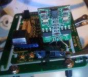
I did small mod and tap ShuntReg directly to feed the XO's. Unfortunately cutting trace was required and that was the hardest part, to cut that beautifully crafted board. But at the end there is shunt reg for XO's and in my case I left switch to be able to test differences between on-board LDO and shunt-reg and next to have open solution to tap LiPo batteries.
Well can say that the results are at list interesting and even more interesting is comparing differences between TentClock and Crystek 957 powered by LDO and ShuntReg.
So it is fun... and seems that in my case Trident will stay.
But actually have two questions.
How about using CCHD 957 XO's Standby Mode ?
That seems to be interesting, we could shut down not used XO, and possibly that could reduce noise and interferences from running two clocks on the same board/power, that possibly matter even while they are nicely decoupled . Well also would lower the power required to run the XO's from batteries.
I have tested that board requires two clocks running to start up... so need Your help/advise with that.
Any back-door to use logic that is already on board to put unused Crystek XO in standby mode in the right time..?
Well and also to start it up during changing frequencies.
Second question is regarding power for fan-out chip's.
They are powered from flip-flops LDO and while MClk to DAC is send not directly from XO's but from fan-out chip's , its power can have influence on clock "quality".
I wonder of Your opinion regarding taping them to XO's shunt reg or XO's "free" LDO. But since that would require much more "surgery" on Your board I fought about asking Your opinion first, seems that You deliberately are using flip-flops LDO to power fan-out chips even while XO LDO is much closer.
Rosendorfer
Actually regarding power for Dual Clock board.
I did small mod and tap ShuntReg directly to feed the XO's. Unfortunately cutting trace was required and that was the hardest part, to cut that beautifully crafted board. But at the end there is shunt reg for XO's and in my case I left switch to be able to test differences between on-board LDO and shunt-reg and next to have open solution to tap LiPo batteries.
Well can say that the results are at list interesting and even more interesting is comparing differences between TentClock and Crystek 957 powered by LDO and ShuntReg.
So it is fun... and seems that in my case Trident will stay.
But actually have two questions.
How about using CCHD 957 XO's Standby Mode ?
That seems to be interesting, we could shut down not used XO, and possibly that could reduce noise and interferences from running two clocks on the same board/power, that possibly matter even while they are nicely decoupled . Well also would lower the power required to run the XO's from batteries.
I have tested that board requires two clocks running to start up... so need Your help/advise with that.
Any back-door to use logic that is already on board to put unused Crystek XO in standby mode in the right time..?
Well and also to start it up during changing frequencies.
Second question is regarding power for fan-out chip's.
They are powered from flip-flops LDO and while MClk to DAC is send not directly from XO's but from fan-out chip's , its power can have influence on clock "quality".
I wonder of Your opinion regarding taping them to XO's shunt reg or XO's "free" LDO. But since that would require much more "surgery" on Your board I fought about asking Your opinion first, seems that You deliberately are using flip-flops LDO to power fan-out chips even while XO LDO is much closer.
Rosendorfer
Attachments
Sorry for my absent last weekend. I was listening to music. The isolation board together with the battery management really made some difference to my system. Kind of enjoymentJ.
I guess testing group already start receiving the PCB. Here are some digikey P/Ns which I didn’t list in the BOM. Just in case you need them.
PH2.0mm terminal pins: 455-1127-2-ND
2P PH2.0mm housing: 455-1165-ND
IC socket to pick up XO pin from: ED2681-ND
I’m looking forward to your good news.
Ian
I guess testing group already start receiving the PCB. Here are some digikey P/Ns which I didn’t list in the BOM. Just in case you need them.
PH2.0mm terminal pins: 455-1127-2-ND
2P PH2.0mm housing: 455-1165-ND
IC socket to pick up XO pin from: ED2681-ND
I’m looking forward to your good news.
Ian
Good job Rosendorfer! That's a wonderful experiencing.Hi Ian
Actually regarding power for Dual Clock board.
I did small mod and tap ShuntReg directly to feed the XO's. Unfortunately cutting trace was required and that was the hardest part, to cut that beautifully crafted board. But at the end there is shunt reg for XO's and in my case I left switch to be able to test differences between on-board LDO and shunt-reg and next to have open solution to tap LiPo batteries.
Well can say that the results are at list interesting and even more interesting is comparing differences between TentClock and Crystek 957 powered by LDO and ShuntReg.
So it is fun... and seems that in my case Trident will stay.
But actually have two questions.
How about using CCHD 957 XO's Standby Mode ?
That seems to be interesting, we could shut down not used XO, and possibly that could reduce noise and interferences from running two clocks on the same board/power, that possibly matter even while they are nicely decoupled . Well also would lower the power required to run the XO's from batteries.
I have tested that board requires two clocks running to start up... so need Your help/advise with that.
Any back-door to use logic that is already on board to put unused Crystek XO in standby mode in the right time..?
Well and also to start it up during changing frequencies.
Second question is regarding power for fan-out chip's.
They are powered from flip-flops LDO and while MClk to DAC is send not directly from XO's but from fan-out chip's , its power can have influence on clock "quality".
I wonder of Your opinion regarding taping them to XO's shunt reg or XO's "free" LDO. But since that would require much more "surgery" on Your board I fought about asking Your opinion first, seems that You deliberately are using flip-flops LDO to power fan-out chips even while XO LDO is much closer.
Rosendorfer
PUS is very very important for the clock board. Please keep good working on the research, you’ll get a lot of discovery. I have a spare TP shunt reg, maybe I can give a try when I get time.
The Dual XO Clock Board already has the XO standby control logic included. If you are running two CCHD951, one is working and the other one will be put into standby mode. Tentclock is the only one exception which doesn’t come with a disable control.
XO is the most important part on the clock board, so it’s better to have independent LDO. Distributing the clock via a funout buffer is a better solution. The additive jitter of the driver is only 29 fs. Please always avoid driving multiple loads or long cable directly from the output of XO which will lower grade the XO performance.
I have another solution which I’m using right now to power the dual XO board: Remove the two on board LDO and short the input and output with two 0 ohm 0805 jumpers (resistor). Then power the dual xo clock board with one 3.2V LiFePO4 battery cell (I’m having a passive battery management board now) from J5 DC input port, but you need an isolator board to avoid short with the FIFO power otherwise you have to remove L11.
Good luck to your project.
Ian
- Home
- Source & Line
- Digital Line Level
- Asynchronous I2S FIFO project, an ultimate weapon to fight the jitter