i've already said above it would perhaps present an advantage doing it all on one board or at least well integrated, but when there is already perfectly good solutions designed by others to use with what hes got already, the only reason would be money. I would be extremely surprised if it measured more than 1db better than what is possible already with modules. a proper and original well performing discrete analogue stage isnt a small undertaking either, I would say this is further out of Ians skillset than the USB.
Since you mention him, Lucien and Acko are already working together on a project, which could be interesting. interesting for others that is, i'm about done with dacs for quite a while I think and I cant justify building another one
If I was going to be bold enough to suggest anything to anyone I'd be suggesting that acko made a combo-board with a mounting position for the FIFO board ...
I wonder if everyone has recognised the significance that Ian has provided rubber mounting rings for the FIFO boards to decouple vibration from the clock circuits especially. Any integrated board that uses this decoupling technique will still be using u.fl/w.fl coax connections for moving the i2s between FIFO output and DAC input.
The value (in terms of performance gains) of an integrated DAC design over an acko combo board with FIFO is what exactly?
The value (in terms of performance gains) of an integrated DAC design over an acko combo board with FIFO is what exactly?
Last edited:
you sir, raise a very good point
one thing that could be cool would be a differential clock driver to get rid of the clock/ground connection as well, but any of that will add jitter, in fact pretty much any isolation technique will, so its kinda 6 one way half a dozen the other for any 'improvements' from this point on
one thing that could be cool would be a differential clock driver to get rid of the clock/ground connection as well, but any of that will add jitter, in fact pretty much any isolation technique will, so its kinda 6 one way half a dozen the other for any 'improvements' from this point on
Last edited:
If I was going to be bold enough to suggest anything to anyone I'd be suggesting that acko made a combo-board with a mounting position for the FIFO board ...
Another flashing idea! I will move the mounting holes a bit on the next version of FIFO PCB, to make a new possible option: clock board stack above the FIFO board. That will save a lot of space for a DAC project.
Nice weekend.
Ian
Ian.
Why don't you built a DAC by yourself?
Instead of tweaking an average 3rd party product you should built your own DAC.
It's just a PIC and a DAC on top of your stuff. Shouldn't be such a big problem for you.
Beacuse you built it better than me
") .
.Ian
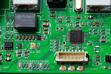
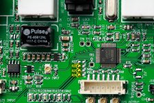
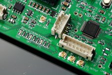
Steps to tap connector header to the reserved I2S input port on the S/PDIF Board
Setp2: Cover the GND pads of R23, R24 and R25 with fine cut high temperature tape to avoid signals short to GND.
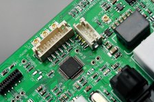
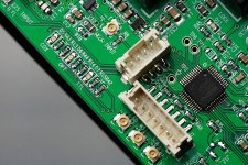
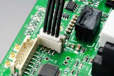
Setp3: Solder the 4P SMT PH2.0 header, Pin1 (WS) to R24 signal pad, Pin2 (SD) to R25 signal pad, Pin3 (SCK) to R23 signal pad and Pin4 to both R22 signal pad and GND pad,
Step4: Cut the solder mask paint beside the both GND pads of the header appearing small area of GND copper plate, please be careful no touching any other circuit route.
Step5: Solder the support pads of the header to the appeared GND copper plate. Solder iron with higher power may require. For enough support force, applying compound of strong glue (such as epoxy) is highly suggested for double support.
Step6: Make an I2S cable to introduce an additional I2S input source.
The Digikey P/Ns are:
Connector header: 455-1736-1-ND
House: 455-1164-ND
Terminal pin: 455-1127-2-ND
Ian
Step1: Remove R22, R23, R24, R25 from PCB. SMT soldering station is recommended tool, but normal solder iron is still OK.
Setp2: Cover the GND pads of R23, R24 and R25 with fine cut high temperature tape to avoid signals short to GND.
Setp3: Solder the 4P SMT PH2.0 header, Pin1 (WS) to R24 signal pad, Pin2 (SD) to R25 signal pad, Pin3 (SCK) to R23 signal pad and Pin4 to both R22 signal pad and GND pad,
Step4: Cut the solder mask paint beside the both GND pads of the header appearing small area of GND copper plate, please be careful no touching any other circuit route.
Step5: Solder the support pads of the header to the appeared GND copper plate. Solder iron with higher power may require. For enough support force, applying compound of strong glue (such as epoxy) is highly suggested for double support.
Step6: Make an I2S cable to introduce an additional I2S input source.
The Digikey P/Ns are:
Connector header: 455-1736-1-ND
House: 455-1164-ND
Terminal pin: 455-1127-2-ND
Ian
Attachments
Last edited:
Thanks Ian for the detailed procedures and effort. Is it possible to include the SMT header/connector in GB2 as it is difficult to just order these few parts from Digikey.
Just let me think about it. I might try to supply the I2S backdoor KIT.
Ian
Thanks Ian for the detailed procedures and effort. Is it possible to include the SMT header/connector in GB2 as it is difficult to just order these few parts from Digikey.
+1 from also from me..
Well or maybe .....
We could use BIII adapter board, any chance to solder in nicely in that position...??
I2S using u.FL.... just a fought.
Rosendorfer
Another flashing idea! I will move the mounting holes a bit on the next version of FIFO PCB, to make a new possible option: clock board stack above the FIFO board. That will save a lot of space for a DAC project.
Nice weekend.
Ian
Ian
Its a good idea but the flat cable is not long enough, please consider to provide a longer version in GBII. I want to stack the SPDIF above the FIFO.
+1 from also from me..
Well or maybe .....
We could use BIII adapter board, any chance to solder in nicely in that position...??
I2S using u.FL.... just a fought.
Rosendorfer
its really not very clear what you are asking for here.
do also remember these are basically being thrown in as a gift with a kit that is already priced VERY low, do you think also asking him to source your parts for you and what solder them too is reasonable, on another 50-100 adapters kits?
IMO someone ELSE should pick up the ball and organize a small GB for these parts
Last edited:
its really not very clear what you are asking for here.
do also remember these are basically being thrown in as a gift with a kit that is already priced VERY low, do you think also asking him to source your parts for you and what solder them too is reasonable, on another 50-100 adapters kits?
IMO someone ELSE should pick up the ball and organize a small GB for these parts
Dear qusp
I will take that You are fighting for a Noble Cause hire.. saving our precious Ian from all the "dark creatures" wondering around this forum, and as justfull sheriff, shot first then ask ... but wish You bit more faith in people...
Love and Peace....
and well ... Jitter Free Musik..
Regards
Rosendorfer
actually no, I asked quite directly first... then shotshot first then ask
what do you think
is? was it because it was missing a question mark? no offense, it really wasnt very clear what it was you were asking, so I asked …qusp said:'its really not very clear what you are asking for here'
then I preempted the dark creatures; they are everywhere


Its not even preemptive, it was already asked on the previous page that he add the parts to the kit and solder them for some, but not others, meaning making another order to cover it one would presume. thats cool Ian can look after himself, but these in particular are something that would be perfect for a group buy for someone else to organize. which thankfully MisteRogers has offered to do (@misterogers: i'll shoot you a pm later mate)
With Loriens board and now looking like the twisted pear guys may offer them as optional connectors now, just generally diyers, the fifo of course … I think there will be quite a few takers for these given how well the price is driven down with bulk order.
They are light and tiny so the postage will be small too.
This Group is getting pretty big now, so leveraging the buying power of a large group for other fifo associated parts becomes attractive. A proactive person might survey what power supply options people were using and combine a GB for the most popular choice. LiFePO4 Batteries would be attractive but the difficulty of shipping pretty much rules them out
i'm all GB'd out for a while, having been involved in running a few already for the better part of this year and last, so its not going to be me, but it damn well shouldnt be Ian.
so i would say the same of you, think first before firing the first shot.
Last edited:
FIFO KIT GB II details posted today
Please click below link to take a look:
http://www.diyaudio.com/forums/grou...s-pdif-fifo-kit-group-buy-40.html#post3093337
Thanks and have a nice week.
Ian
Please click below link to take a look:
http://www.diyaudio.com/forums/grou...s-pdif-fifo-kit-group-buy-40.html#post3093337
Thanks and have a nice week.
Ian
Question Ian; I'm playing with the eXD USB/PCM/DSD board. I've had the firmware flashed to switch the ESS9018 (Buffalo or Acko, whatever) between I2S & DSD depending on the stream. Driving the Buffalo directly, it demonstrates the sonic advantages of DSD direct (IMO). Audirvana Plus is using the DSD over PCM standard when playing DSD files. If I place FIFO between the eXD board and the ESS*, how will FIFO react? Will it simply drop stream when DSD comes through? Will it pass through? I'm sure there's much going on here that I don't understand - so apologies in advance for my stupidity
Dual XO board -
Hello Ian,
first, thank you for sharing your fabulous project and for the great job to organize the GB.
In the search for alternatives to Crystek's XO, I would like to know if NDK's oscillators, 90.3168 MHz & 98,304 Mhz, are "compatible" with Dual XO clock board.
Those XOs would prevent the double speed mode.
If your answer is affermative, please let us know the right settings.
I attach the datasheet.
Greetings
hirez69
Attachments
Morning! (at least for me Yea, I know FIFO doesn't do DSD, I was more curious as to whether it might 'pass through' DSD. I'm also curious about about how the DSD over PCM 1.0 spec. will 'play' with FIFO. I'm using an eXD PCM/DSD board in one of my builds that's using this spec.
Yea, I know FIFO doesn't do DSD, I was more curious as to whether it might 'pass through' DSD. I'm also curious about about how the DSD over PCM 1.0 spec. will 'play' with FIFO. I'm using an eXD PCM/DSD board in one of my builds that's using this spec. MisteRogers: no the fifo will not do DSD
- Home
- Source & Line
- Digital Line Level
- Asynchronous I2S FIFO project, an ultimate weapon to fight the jitter