Buffalo III sync mode interface PCB KIT design
I forgot who gave me this suggestion. But with running at sync mode, my own experiencing shows current BIII input port and the local XO adapter still have space getting some improvement for the last drop of juice 🙂 . So I designed this PCB KIT. Actuall two adapters integrated together.
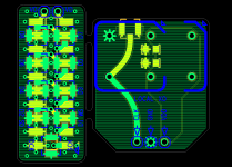
One is the input adapter. I put a 20P SMT head on the bottom side to get connect with B III, on the top side, there is a group of U.FL connectors which could improve the signal quality. For stereo I2S aplication, only three U.FL socket are required. Because at the sync mode, ESS9018 still very sensitive to the input I2S sck, improving the signal transmitting quality is very important.
The other one is the local clock adapter. It will be soldered vertically right above the local clock position by a right angle 3P connector pins. If you put a local XO (make use of the 100Mhz CCHD950 for example) into the socket, ESS9018 will run at async mode. or, If you want to run the sync mode, you just need to remove the local XO from the socket and connect the MCLK cable from FIFO clock board into the U.FL socket on the adapter PCB. So, you can switch between the two mode quickly to enjoy both, or doing some listing compare.
Ian
I forgot who gave me this suggestion. But with running at sync mode, my own experiencing shows current BIII input port and the local XO adapter still have space getting some improvement for the last drop of juice 🙂 . So I designed this PCB KIT. Actuall two adapters integrated together.
One is the input adapter. I put a 20P SMT head on the bottom side to get connect with B III, on the top side, there is a group of U.FL connectors which could improve the signal quality. For stereo I2S aplication, only three U.FL socket are required. Because at the sync mode, ESS9018 still very sensitive to the input I2S sck, improving the signal transmitting quality is very important.
The other one is the local clock adapter. It will be soldered vertically right above the local clock position by a right angle 3P connector pins. If you put a local XO (make use of the 100Mhz CCHD950 for example) into the socket, ESS9018 will run at async mode. or, If you want to run the sync mode, you just need to remove the local XO from the socket and connect the MCLK cable from FIFO clock board into the U.FL socket on the adapter PCB. So, you can switch between the two mode quickly to enjoy both, or doing some listing compare.
Ian
Attachments
Last edited:
Ian that's fantastic! I'm waiting for my BIII, FIFO, etc. to land and I plan to follow in your steps with these modes. What are your thoughts with this board? Or more directly - how can I and other BIII builders get their hands on one of these?
I forgot who gave me this suggestion. But with running at sync mode, my own experiencing shows current BIII input port and the local XO adapter still have space getting some improvement for the last drop of juice 🙂 . So I designed this PCB KIT. Actuall two adapters integrated together.
One is the input adapter. I put a 20P SMT head on the bottom side to get connect with B III, on the top side, there is a group of U.FL connectors which could improve the signal quality. For stereo I2S aplication, only three U.FL socket are required. Because at the sync mode, ESS9018 still very sensitive to the input I2S sck, improving the signal transmitting quality is very important.
The other one is the local clock adapter. It will be soldered vertically right above the local clock position by a right angle 3P connector pins. If you put a local XO (make use of the 100Mhz CCHD950 for example) into the socket, ESS9018 will run at async mode. or, If you want to run the sync mode, you just need to remove the local XO from the socket and connect the MCLK cable from FIFO clock board into the U.FL socket on the adapter PCB. So, you can switch between the two mode quickly to enjoy both, or doing some listing compare.
Ian
Ian
Great Job. Although I managed to solder the U.FL sockets onto the BIII PCB, but all three sockets are broken when I tried to disconnect the cables.
One suggestion, is it possible to modify the PCB so that it can switch between two I2S source (e.g. FIFO + WaveIO)? Or I can use the Sidecar with two PCB?
I forgot who gave me this suggestion. But with running at sync mode, my own experiencing shows current BIII input port and the local XO adapter still have space getting some improvement for the last drop of juice 🙂 . So I designed this PCB KIT. Actuall two adapters integrated together.
Nice work Ian! 😉
Could you give any details on how you're terminating that i2s from u.fl into the pin female pin header? Have you had any thoughts on how to improve the situation at the DAC end of that interface? I've had thoughts about making a small pcb to convert pin headers to u.fl sockets and would appreciate your thoughts/experiences. I guess there is probably a bunch of other people in this thread looking to interface this board to DACs that don't always have ideal methods for connecting the i2s signal.
For anyone else who's interested I have emailed TPA about BIII being supplied without onboard XO and they aren't able to provide this so you've got to remove them yourself if you want to follow Ian, qusp and others recommendation to remove it.
Nice work Ian! 😉
For anyone else who's interested I have emailed TPA about BIII being supplied without onboard XO and they aren't able to provide this so you've got to remove them yourself if you want to follow Ian, qusp and others recommendation to remove it.
Thanks hochoperper, I remember now it was you who provided this suggestion.
At beginning I thought it would be very hard to achieve. But when I realized this problem has to be solved, I got an idea mounting the header and u.fl on the different side of the adapter. It seems OK. I will make some prototype PCB the next.
Ian
Ian, thats great mate, any chance of putting the 2.54mm positions in between? i've been wanting to make exactly this for interfacing with titan, which has RJ45 or strip header. actually looking at it, the BIII uses 2.54 strip headers now doesnt it? I would use this for interfacing titan, which has RJ45, or strip header
bad idea, high speed switching is not a simple task and will ruin performance for both devices. you must do this actively, passive switching will ruin impedance terminationIan
Great Job. Although I managed to solder the U.FL sockets onto the BIII PCB, but all three sockets are broken when I tried to disconnect the cables.
One suggestion, is it possible to modify the PCB so that it can switch between two I2S source (e.g. FIFO + WaveIO)? Or I can use the Sidecar with two PCB?
Thanks hochoperper, I remember now it was you who provided this suggestion.
At beginning I thought it would be very hard to achieve. But when I realized this problem has to be solved, I got an idea mounting the header and u.fl on the different side of the adapter. It seems OK. I will make some prototype PCB the next.
Ian
yeah and you'll never guess who made the suggestion to him =)


bad idea, high speed switching is not a simple task and will ruin performance for both devices. you must do this actively, passive switching will ruin impedance termination
Thanks for your advice.
Ian, I somehow missed that:
Are your S/PDIF inputs galvanically isolated? Hooking up a noisy source/ground (eg a PC) to the FIFO without galvanically isolate it isn't really what one would like...
And the optical input will make "only" 96kHz.
Are your S/PDIF inputs galvanically isolated? Hooking up a noisy source/ground (eg a PC) to the FIFO without galvanically isolate it isn't really what one would like...
And the optical input will make "only" 96kHz.
Hi,
Have you seen Naim audio products? it sounds FIFO is great idea 🙂-).
Ian, Is it so that output clck frequency is adjust to input clck in order to not run out or full the FIFO ? how can it be done as output clock is at a fixed frequency ?
About galvanical isolation, have you seen AD icoupler ? also there are some advices about PCB design in AN-1109, does it makes senses with FIFO board ?
have a nice evening
anaeroben
I also want to switch between two sources and I was thinking about these options (in this order):bad idea, high speed switching is not a simple task and will ruin performance for both devices. you must do this actively, passive switching will ruin impedance termination
1. use one of Omron's G6Z high-frequency relays with 50ohm impedance
2. Use two Potato semi PO74G125A buffers and switch by their OE pin
3. Use a high frequency bus switch like PO3B3257A
Which of the above or else would you recommend?
Thanks.
Ian, I somehow missed that:
Are your S/PDIF inputs galvanically isolated? Hooking up a noisy source/ground (eg a PC) to the FIFO without galvanically isolate it isn't really what one would like...
And the optical input will make "only" 96kHz.
Hi zinsula,
For the S/PDIF input, usually I like OPT, it isolate electronic signal natually. The good thing is, with the FIFO, there is no difference between OPT and COX input.
However, to use the COX input, most of the digital source, even the USB sound cards, equiped with digital transformer, which also isolate the ground and most of the EMI noise. Don't use the COX S/PDIF source without transformer.
Regards,
Ian
...Don't use the COX S/PDIF source without transformer
Hi Ian, exactly, that was my point. I have to check whether my source i was thinking to use has a transformer output.
If its OK, i may need the SPDIF board. I'll not be able to tell WM8804 to accept 176.4....so your TI DX.... receiver comes in handy 🙂
Ciao, Tino
Hi Ian, exactly, that was my point. I have to check whether my source i was thinking to use has a transformer output.
If its OK, i may need the SPDIF board. I'll not be able to tell WM8804 to accept 176.4....so your TI DX.... receiver comes in handy 🙂
Ciao, Tino
Actually I did evaluation on both before I made decision. Trust me, DIX9211, very good indeed, especially for higher Fs 🙂.
Ian
Last edited:
Hi,
Have you seen Naim audio products? it sounds FIFO is great idea 🙂-).
Ian, Is it so that output clck frequency is adjust to input clck in order to not run out or full the FIFO ? how can it be done as output clock is at a fixed frequency ?
About galvanical isolation, have you seen AD icoupler ? also there are some advices about PCB design in AN-1109, does it makes senses with FIFO board ?
have a nice evening
anaeroben
That's true. The FIFO concept really works for eliminating the jitter from digital music. The reason I could use a fixed frequency secondary clock is, there is a big enough memeory equiped on board. So, it a true FIFO 🙂.
If you want to make the secondary clock following up the input clock, you will increase jitter.
Regards,
Ian
Ian, I somehow missed that:
Are your S/PDIF inputs galvanically isolated? Hooking up a noisy source/ground (eg a PC) to the FIFO without galvanically isolate it isn't really what one would like...
And the optical input will make "only" 96kHz.
the optical input isnt limited to 96khz, your optical output is, haha I just noticed there is no tx on the input (i've only used optical or i2s) so ya I get your point.
Last edited:
I also want to switch between two sources and I was thinking about these options (in this order):
1. use one of Omron's G6Z high-frequency relays with 50ohm impedance
2. Use two Potato semi PO74G125A buffers and switch by their OE pin
3. Use a high frequency bus switch like PO3B3257A
Which of the above or else would you recommend?
Thanks.
2 I think, with termination on the input, well I cant advise on 3 or 1as I have no experience with them, though 1 sounds interesting, I would worry about linearity, but i'm a bit of a 'worry wart'
- Home
- Source & Line
- Digital Line Level
- Asynchronous I2S FIFO project, an ultimate weapon to fight the jitter