hehe expert, the people here I call experts put me to shame! but yes do that first and allow room for shunt or battery for the clock board. powering the clock board or clocks and flip flops directly with upgraded power may be more worthwhile, wont create as much heat and wont require such significant heatsinking. try powering the whole thing with linear or battery first and then upgrade the clock board supplies as an upgrade, if you dont hear the difference of that, then I dont believe you will hear it for powering the whole thing. also consider Demians regulator design
Last edited:
Successfully running ESS9018 (Buffalo III) at synchronized mode
I hooked up the FIFO KIT and B III into synchronized configuration yesterday. It runs great without any problem. The setup is easier than I thought. Please see the attached pictures for details(find the names for the meaning of the pictures).
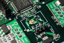
Step1: Remove the CCHD950 OEM 100Mhz local oscillator
After the CCHD950 was removed, I found TP has already left a backdoor for the sync mode. There is a 3 pin socket underneath, GND, VDDXO and CLOCK
Tips: protect the surrounding component with thermal tape and heat the back of the PCB first to avoid any possible damage.
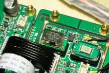
Step2: Assemble a U.FL socket
I still think U.FL socket is better for the clock signals, so I just soldered it on the BIII board. Signal (MCLK input) to CLOCK and shield to GND. However, using the 3 pin dip connector will make it easier switching between sync and async mode, so later on, maybe I have to give up the U.FL socket and switch back to 3 pin dip connector.
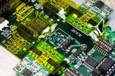
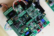
Step3: set up the Dual XO Clock board into double speed mode with 45.1584 MHz and 49.1520 MHz oscillators.
Please see the attached PDF guidance for details. Please be notice, jumpers have to be set exactly as what directed in the doc. Actually I finished this document 6 weeks ago, but I have to confirm it by myself before I public it.
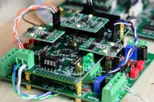
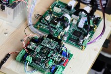
Step4: connecting the cables
I2S output to I2S input, MCLK output to MCLK input.
Step5: Enjoy the music.
It runs right away without any hesitating. The LOCK LED keeps lighting all the way indicating it synchronized with the input I2S stream unconditional even I set the bandwidth switches to 'lowest' and run music at 192KHz from an USB.
According to my understanding on the ESS9018 sync mode:
1, The DAC is running by the MCLK directly no matter what mode it is, sync or async, DPLL is only used for re-sampling job according to the ASRC algorithm , it doesn't generate any real clock;
2, In the async mode, DPLL re-samples the input I2S asynchronizely, the bandwidth of the DPLL could not go infinite to lock with input I2S due to the phase difference between clocks. With the limited bandwidth, all jitter below will be path through and converted into re-sampling jitter and all above will be removed and determined by the MCLK.
3, In the sync mode, DPLL locks to input I2S un-conditionally with infinite (even better than the 'lowest') bandwidth because the I2S is generated by same MCLK with fixed relationship of 256*,512*,1024* and so on. In this case, the DAC jitter is 100% determined by MCLK itself, so the finial sound will be highly depend on the FIFO clock.
In my configuration, ESS9018 sounds great in both of the modes, sync and async. I even couldn't tell which one is better. But there is slightly difference on the sound style. Async is more like ESS9018 J while sync is more like classical high-end DACs. I usually don't talk much about the sound, because too many psychological factors and personal feelings mixed. I'll left this part to others, trust your ears and try to find out the best parameter settings of 9018 for the sync mode.
90.3168MHz and 98.3040MHz would be more optimized frequency for ESS9018, but it’s very hard to find out the really nice XOs with those frequencies so far, except the si570 based real time programmable low jitter XO I could think about.
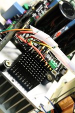
I added an additional piece of heat sink and make it facing up. The stable working temp on the surface reduced from 60C to 53C J.
Have a nice weekend.
Ian
I hooked up the FIFO KIT and B III into synchronized configuration yesterday. It runs great without any problem. The setup is easier than I thought. Please see the attached pictures for details(find the names for the meaning of the pictures).
Step1: Remove the CCHD950 OEM 100Mhz local oscillator
After the CCHD950 was removed, I found TP has already left a backdoor for the sync mode. There is a 3 pin socket underneath, GND, VDDXO and CLOCK
Tips: protect the surrounding component with thermal tape and heat the back of the PCB first to avoid any possible damage.
Step2: Assemble a U.FL socket
I still think U.FL socket is better for the clock signals, so I just soldered it on the BIII board. Signal (MCLK input) to CLOCK and shield to GND. However, using the 3 pin dip connector will make it easier switching between sync and async mode, so later on, maybe I have to give up the U.FL socket and switch back to 3 pin dip connector.
Step3: set up the Dual XO Clock board into double speed mode with 45.1584 MHz and 49.1520 MHz oscillators.
Please see the attached PDF guidance for details. Please be notice, jumpers have to be set exactly as what directed in the doc. Actually I finished this document 6 weeks ago, but I have to confirm it by myself before I public it.
Step4: connecting the cables
I2S output to I2S input, MCLK output to MCLK input.
Step5: Enjoy the music.
It runs right away without any hesitating. The LOCK LED keeps lighting all the way indicating it synchronized with the input I2S stream unconditional even I set the bandwidth switches to 'lowest' and run music at 192KHz from an USB.
According to my understanding on the ESS9018 sync mode:
1, The DAC is running by the MCLK directly no matter what mode it is, sync or async, DPLL is only used for re-sampling job according to the ASRC algorithm , it doesn't generate any real clock;
2, In the async mode, DPLL re-samples the input I2S asynchronizely, the bandwidth of the DPLL could not go infinite to lock with input I2S due to the phase difference between clocks. With the limited bandwidth, all jitter below will be path through and converted into re-sampling jitter and all above will be removed and determined by the MCLK.
3, In the sync mode, DPLL locks to input I2S un-conditionally with infinite (even better than the 'lowest') bandwidth because the I2S is generated by same MCLK with fixed relationship of 256*,512*,1024* and so on. In this case, the DAC jitter is 100% determined by MCLK itself, so the finial sound will be highly depend on the FIFO clock.
In my configuration, ESS9018 sounds great in both of the modes, sync and async. I even couldn't tell which one is better. But there is slightly difference on the sound style. Async is more like ESS9018 J while sync is more like classical high-end DACs. I usually don't talk much about the sound, because too many psychological factors and personal feelings mixed. I'll left this part to others, trust your ears and try to find out the best parameter settings of 9018 for the sync mode.
90.3168MHz and 98.3040MHz would be more optimized frequency for ESS9018, but it’s very hard to find out the really nice XOs with those frequencies so far, except the si570 based real time programmable low jitter XO I could think about.
I added an additional piece of heat sink and make it facing up. The stable working temp on the surface reduced from 60C to 53C J.
Have a nice weekend.
Ian
Attachments
-
 RemoveCCHD950.JPG738.8 KB · Views: 1,080
 -
 AssembleU.FL.JPG524.1 KB · Views: 960
 -
 DoubleSpeedClocks.JPG583.8 KB · Views: 947
 -
 BIIIinSyncMode.JPG522 KB · Views: 901
 -
 SyncModeHookup.JPG547.6 KB · Views: 890
 -
 AddSomeHeatsink.JPG480.8 KB · Views: 571
 -
DuobleSpeedModeDualXOclockBoard.zip69.5 KB · Views: 195
-
 LockAtLowestBandwidth.JPG638 KB · Views: 574
Last edited:
good job! yeah no magic to sync mode, you just need the right clock/i2s source.
guess i'll still be sending it back for quad mode setting
i've been meaning to ask mate, where do you get this spiral cable-wrap stuff? i've not seen it before your builds and it seems very handy
guess i'll still be sending it back for quad mode setting
i've been meaning to ask mate, where do you get this spiral cable-wrap stuff? i've not seen it before your builds and it seems very handy
Great post Ian! Especially the pics showing the area of interest on the BIII very clearly, sometimes quite hard to get those tiny areas in focus properly.
It seems like a miniaturised version of - Zone Hardware Large Cord Wrap 2m at $11.96 in Cable Organisers
I'm not sure where you get them to suit smaller cables I've only seen it on bundles of larger cables rather than individual wires that look like they're closer to 24awg.
i've been meaning to ask mate, where do you get this spiral cable-wrap stuff? i've not seen it before your builds and it seems very handy
It seems like a miniaturised version of - Zone Hardware Large Cord Wrap 2m at $11.96 in Cable Organisers
I'm not sure where you get them to suit smaller cables I've only seen it on bundles of larger cables rather than individual wires that look like they're closer to 24awg.
Just thought that I would add this link in here for anyone wanting to use FIFO dual XO as external master clock to BIII.
On the twisted pear forums Brian suggests simply removing power to the onboard clock and connecting to the pin headers from underside of the BIII and leaving the onboard 100MHz CCHD950 in place unpowered.
Do you have any thoughts on that Ian?
On the twisted pear forums Brian suggests simply removing power to the onboard clock and connecting to the pin headers from underside of the BIII and leaving the onboard 100MHz CCHD950 in place unpowered.
Do you have any thoughts on that Ian?
yeah thats belden networking cable 1583A if i'm not mistaken and it is indeed 24awg solid copper internally
heres some
but I shudder to think of the shipping fee, these places usualy ream you. found something similar here in AU but its not as useful. the one you linked is no good. the ones above go down to internal diameter of 1/8" up to 3" but the 1/4 or 3/8 seems perfect.
Ian is already aware of that clock business, I also mentioned it on the previous page or before. it will work and thats what i'm doing at the moment, but the crystek doesnt have a shutdown mode, so leaving it unpowered means whatever is hanging off the end of the clock circuit in its 'HiZ mode' internally is in parallel with the input clock. also wiuth the clock there there isnt really anywhere convenient on the b3 to connect anything but bare wire unlike on the ackodac and buff II
Last edited:
...
90.3168MHz and 98.3040MHz would be more optimized frequency for ESS9018, but it’s very hard to find out the really nice XOs with those frequencies so far, except the si570 based real time programmable low jitter XO I could think about.
...Ian
Seem a frequency of 40Mhz is optimized for the DAC: http://www.diyaudio.com/forums/digi...e-reference-dac-8-channel-61.html#post1441042
In addition, try turning oversampling On/Off...
Just thought that I would add this link in here for anyone wanting to use FIFO dual XO as external master clock to BIII.
On the twisted pear forums Brian suggests simply removing power to the onboard clock and connecting to the pin headers from underside of the BIII and leaving the onboard 100MHz CCHD950 in place unpowered.
Do you have any thoughts on that Ian?
How about an IC output pin without power up? If there is ESD protecting diode.... the new clock signal will be suffer....and consider the empty pin as a capacitive load .... for a RF signal like a clock....also no good. Yes, my point is... you have to remove it
") .
.Ian is already aware of that clock business, I also mentioned it on the previous page or before. it will work and thats what i'm doing at the moment, but the crystek doesnt have a shutdown mode, so leaving it unpowered means whatever is hanging off the end of the clock circuit in its 'HiZ mode' internally is in parallel with the input clock. also wiuth the clock there there isnt really anywhere convenient on the b3 to connect anything but bare wire unlike on the ackodac and buff II
Now you mention that I remember that post you mention, I didn't see the significance at the time since I hadn't looked at the BIII layout other than the main photo on the TPA site which really didn't show the juicy details.
How about an IC output pin without power up? If there is ESD protecting diode.... the new clock signal will be suffer....and consider the empty pin as a capacitive load .... for a RF signal like a clock....also no good. Yes, my point is... you have to remove it
When you put it that way ...
It seems like some may be better off convincing TPA to ship the BIII with the CCHD950 not mounted at all.
Seem a frequency of 40Mhz is optimized for the DAC: http://www.diyaudio.com/forums/digi...e-reference-dac-8-channel-61.html#post1441042
In addition, try turning oversampling On/Off...
he didnt say that, yes the demo board comes with 40Mhz but the dac was specified to run MAX 192 and async mode. the maybe yes, maybe not 1db loss he mentions will only be because of increased thermal, voltage and current noiseI would think. seems its a bit of a different sitruation we are now in, using the dac beyond its initial spec in sync mode with 384+ sources that didnt exists at the time of the dacs inception
yup, i'll be removing mine once the testing phase is over ; I probably should have actually just sent my dac boards down to acko when I sent the MCUs for update given I cant use them while they are gone anyway. but while testing different stuff out its handy to be able to use either mode and connect sources without HAVING to have the fifo inline, particularly while its still not updated to accept higher speedsHow about an IC output pin without power up? If there is ESD protecting diode.... the new clock signal will be suffer....and consider the empty pin as a capacitive load .... for a RF signal like a clock....also no good. Yes, my point is... you have to remove it
Last edited:
he didnt say that, yes the demo board comes with 40Mhz but the dac was specified to run MAX 192 and async mode. the maybe yes, maybe not 1db loss he mentions will only be because of increased thermal, voltage and current noiseI would think. seems its a bit of a different sitruation we are now in, using the dac beyond its initial spec in sync mode with 384+ sources that didnt exists at the time of the dacs inception
...
The message is that Crystek's best clocks are available in this range...
he didnt say that, yes the demo board comes with 40Mhz but the dac was specified to run MAX 192 and async mode. the maybe yes, maybe not 1db loss he mentions will only be because of increased thermal, voltage and current noiseI would think. seems its a bit of a different sitruation we are now in, using the dac beyond its initial spec in sync mode with 384+ sources that didnt exists at the time of the dacs inception
yup, i'll be removing mine once the testing phase is over ; I probably should have actually just sent my dac boards down to acko when I sent the MCUs for update given I cant use them while they are gone anyway. but while testing different stuff out its handy to be able to use either mode and connect sources without HAVING to have the fifo inline, particularly while its still not updated to accept higher speeds
I'm thinking about come back to the 3 pin dip connector for the reserved position, so that I can switch between sync and async mode quickly for compairing the sound between...
.I think the only way to do such a thing accurately is with a switch tbh. i'm more comparing titan with/without fifo and i'm still stuck really, much as I like the idea of the fifo in my main rig; it cant work with anything but my headphone amps until a multichannel fifo comes about. is there any way I can use 2 fifo main boards, for 4 channel with a single dual clock board? in my previous experiments I have found sync mode to be a bit more cohesive, soundstage is more solid, similar to your impressions. how much of this is because of being able to use lowest setting on PLL i'm not sure
the problem with setting up the fifo clock boatrd as the master clock without this functionality means I would have to devise a way to switch master clocks and have a second master clock for multichannel operation, because the fifo clock board will not work standalone without the control signals from the fifo main board.
complicated...
its doubtful performance is better in async mode given the quality of clock and i2s source is allowing you to use lowest, but I suppose it might be subjectively preferred. if it were me in your position, I think I would just turn my gaze back towards clocks and forget about the distraction of sync vs async
Last edited:
I'm certainly not the expert here but ... isn't the final reclocked i2s output leaving from the dual xo board? I agree you're in a bit of a bind here for multichannel.is there any way I can use 2 fifo main boards, for 4 channel with a single dual clock board?
Are you talking 2 x ES9012 or 4 ch output from 1 x ES9018? I think I know which but wanted to ask.
in my previous experiments I have found sync mode to be a bit more cohesive, soundstage is more solid, similar to your impressions. how much of this is because of being able to use lowest setting on PLL i'm not sure

if it were me in your position, I think I would just turn my gaze back towards clocks and forget about the distraction of sync vs async
I concur.
Last edited:
ahh yes of course youre right, wasnt thinking that through, not something I had considered before, so its impossible, cant use this in my rig for speakers. perhaps I could clock another set of flipflops on a little daughterboard, but sounds like a pita.
Chris, you know what dacs ive got..dont you? 2 x 9012
Chris, you know what dacs ive got..dont you? 2 x 9012
I hooked up the FIFO KIT and B III into synchronized configuration yesterday. It runs great without any problem. The setup is easier than I thought. Please see the attached pictures for details(find the names for the meaning of the pictures).
Step1: Remove the CCHD950 OEM 100Mhz local oscillator
After the CCHD950 was removed, I found TP has already left a backdoor for the sync mode. There is a 3 pin socket underneath, GND, VDDXO and CLOCK
Tips: protect the surrounding component with thermal tape and heat the back of the PCB first to avoid any possible damage.
Ian,
That is awesome job. Thank you for sharing.
I have 1 question: if I have a system with BIII duo mono, in theory, can the FIFO clock feed to 2 boards? Or i should use another clock board for this purpose? Thank you.
-coolhead
Step2: Assemble a U.FL socket
I still think U.FL socket is better for the clock signals, so I just soldered it on the BIII board. Signal (MCLK input) to CLOCK and shield to GND. However, using the 3 pin dip connector will make it easier switching between sync and async mode, so later on, maybe I have to give up the U.FL socket and switch back to 3 pin dip connector.
Step3: set up the Dual XO Clock board into double speed mode with 45.1584 MHz and 49.1520 MHz oscillators.
Please see the attached PDF guidance for details. Please be notice, jumpers have to be set exactly as what directed in the doc. Actually I finished this document 6 weeks ago, but I have to confirm it by myself before I public it.
Step4: connecting the cables
I2S output to I2S input, MCLK output to MCLK input.
Step5: Enjoy the music.
It runs right away without any hesitating. The LOCK LED keeps lighting all the way indicating it synchronized with the input I2S stream unconditional even I set the bandwidth switches to 'lowest' and run music at 192KHz from an USB.
According to my understanding on the ESS9018 sync mode:
1, The DAC is running by the MCLK directly no matter what mode it is, sync or async, DPLL is only used for re-sampling job according to the ASRC algorithm , it doesn't generate any real clock;
2, In the async mode, DPLL re-samples the input I2S asynchronizely, the bandwidth of the DPLL could not go infinite to lock with input I2S due to the phase difference between clocks. With the limited bandwidth, all jitter below will be path through and converted into re-sampling jitter and all above will be removed and determined by the MCLK.
3, In the sync mode, DPLL locks to input I2S un-conditionally with infinite (even better than the 'lowest') bandwidth because the I2S is generated by same MCLK with fixed relationship of 256*,512*,1024* and so on. In this case, the DAC jitter is 100% determined by MCLK itself, so the finial sound will be highly depend on the FIFO clock.
In my configuration, ESS9018 sounds great in both of the modes, sync and async. I even couldn't tell which one is better. But there is slightly difference on the sound style. Async is more like ESS9018 J while sync is more like classical high-end DACs. I usually don't talk much about the sound, because too many psychological factors and personal feelings mixed. I'll left this part to others, trust your ears and try to find out the best parameter settings of 9018 for the sync mode.
90.3168MHz and 98.3040MHz would be more optimized frequency for ESS9018, but it’s very hard to find out the really nice XOs with those frequencies so far, except the si570 based real time programmable low jitter XO I could think about.
I added an additional piece of heat sink and make it facing up. The stable working temp on the surface reduced from 60C to 53C J.
Have a nice weekend.
Ian
Sorry guys, I realized that I screw-up the reply, this is my message.
________________________________________
Ian,
That is awesome job. Thank you for sharing.
I have 1 question: if I have a system with BIII duo mono, in theory, can the FIFO clock feed to 2 boards? Or i should use another clock board for this purpose? Thank you.
-coolhead
________________________________________
Ian,
That is awesome job. Thank you for sharing.
I have 1 question: if I have a system with BIII duo mono, in theory, can the FIFO clock feed to 2 boards? Or i should use another clock board for this purpose? Thank you.
-coolhead
it can, but you wouldnt be able to use the spdif board, or if you did you would have to work out some other way of sending Mclk back to it. I was meaning to mention that before you go to press on the next run mate, you should really duplicate one of those clock outputs, probably doesnt need another driver if thats a big deal
Sorry guys, I realized that I screw-up the reply, this is my message.
________________________________________
Ian,
That is awesome job. Thank you for sharing.
I have 1 question: if I have a system with BIII duo mono, in theory, can the FIFO clock feed to 2 boards? Or i should use another clock board for this purpose? Thank you.
-coolhead
There are 2 U.FL MCLK output sockets on the Dual XO Clock Board, so I don't think you have any problem feed them into two dacs. You don't need feed the MCLK to S/PDIF Interface Board if you don't use the DIT function, or you may connect it directly to the U.FL socket on the FIFO board. However, your have to make the I2S cable with branch by yourself.
Last edited:
- Home
- Source & Line
- Digital Line Level
- Asynchronous I2S FIFO project, an ultimate weapon to fight the jitter