Thanks hochopeper,
Like my Salas shunts? The temperature goes up to 60 degree C after 2 hours running, is that safe enough?
where was this temperature taken? the es9018 should not be operated at higher than ambient ~70c and should be below. given you are on breadboard I gather you mean the heatsink? how about the current set resistor temp?
solder it under the board of courseThe best way is solder the u.fl direct to the board as qusp did, but how about those already has the connecter soldered on board
Ian, as for the DPLL, as I understand it, its never turned off completely in a 'sync mode', but the closer BCK becomes to in sync with MCK, it has to do less and less work, until it is completely inactive when both come from the same source. so to be really picky about it, you should use the same length cables for i2s and mclk for ess, not just close as in the fifo manual; even if it means the cables must do a small 'loop' back to the inputs
Last edited:
where was this temperature taken?
solder it under the board of course
Ian, as for the DPLL, as I understand it, its never turned off completely in a 'sync mode', but the closer BCK becomes to in sync with MCK, it has to do less and less work, until it is completely inactive when both come from the same source. so to be really picky about it, you should use the same length cables for i2s and mclk for ess, not just close as in the fifo manual; even if it means the cables must do a small 'loop' back to the inputs
What a smart idea, Yes, solder it under the board!
BTW, the ~70C was measured at the heat sink of the shunt reg
.use "lowest" Block 1 switches 5, 6, 7: On, OFF, OFF
When I use "lowest" and the source is a FPGA based I2S, I have to wait about one hour for the DAC to warm up; otherwise I get drop-offs (the DPLL looses synch)
Yes, when I set the switch to "lowest", I got drop-offs too. It's sound a littlt bit better for me, but I gave up after half hour 'warm up'
.BTW, the ~70C was measured at the heat sink of the shunt reg
That 3 regs carrying heatsink temp sounds high enough. When fins are facing down it ain't helping. Better to fix upright for improved convection or even to force cool it through the fins with a low speed silent fan.
Those boards and Mosfets are tough, but for long term reliability the things to keep in check are the core temp in the semis and the temp on the lytics, in any kind of electronics build. The Mosfets in this kind of reg have an RthJC of 6.3C/W. Means for every Watt they burn, their core climbs 6.3C hotter than their shell. Their silicon junction core meltdown point is 150C and its good they stay under a line of 100C long term. By probing their shell with a thermocouple or by aiming it with an IR thermo gun, plus knowing what voltage and current each one runs you can estimate their core temps. Say you measure 50C on a Mosfet case that runs 0.5A at 5V, its core is at 65.75C for example.
Check the temps on the electrolytics too, should not let climb near their rated temp as printed on their sleeves. Rule of thumb, when halving temp you quadruple long term reliability in electronics. Revisit the thermal plan if ever to box it up because then the ambient temp and convection are gonna get tougher issues IMHO. Nice build by the way, nice configuration. Enjoy.
Yes, when I set the switch to "lowest", I got drop-offs too.
May I ask which DPLL Bandwidth parameter is the best notch you obtained for the play of 192kHz/24bit PCM through the I2S signal path employing your FPGA (The minimum DPLL Bandwidth parameter to maintain a stable lock.) ? "Medium Low" or "Low"?
That 3 regs carrying heatsink temp sounds high enough. When fins are facing down it ain't helping. Better to fix upright for improved convection or even to force cool it through the fins with a low speed silent fan.
Those boards and Mosfets are tough, but for long term reliability the things to keep in check are the core temp in the semis and the temp on the lytics, in any kind of electronics build. The Mosfets in this kind of reg have an RthJC of 6.3C/W. Means for every Watt they burn, their core climbs 6.3C hotter than their shell. Their silicon junction core meltdown point is 150C and its good they stay under a line of 100C long term. By probing their shell with a thermocouple or by aiming it with an IR thermo gun, plus knowing what voltage and current each one runs you can estimate their core temps. Say you measure 50C on a Mosfet case that runs 0.5A at 5V, its core is at 65.75C for example.
Check the temps on the electrolytics too, should not let climb near their rated temp as printed on their sleeves. Rule of thumb, when halving temp you quadruple long term reliability in electronics. Revisit the thermal plan if ever to box it up because then the ambient temp and convection are gonna get tougher issues IMHO. Nice build by the way, nice configuration. Enjoy.
Thanks Salas,
It seems I need add more heatsink to lower the temp. Yes, you are right, the fins facing down no good for radiating the heat but I have no choice
.Or, maybe, open a window underneath.
BTW, I like your regs, very thoughtful design with good performance. I bought three sets from the GB
.Regards,
Ian
May I ask which DPLL Bandwidth parameter is the best notch you obtained for the play of 192kHz/24bit PCM through the I2S signal path employing your FPGA (The minimum DPLL Bandwidth parameter to maintain a stable lock.) ? "Medium Low" or "Low"?
Hi Bunpei,
I have to set bandwidth to 'low-middle' to achieve long term stable lock with 192Khz I2S.
Ian
I just got time this weekend playing with my ESS9018 DAC.
My system:
B&W 804, Pass A5, Pass 1.7, Buffalo III, LegatoIV,SalasShuntReg...
Hi Ian
I am also planning to use the SalasShuntReg to power the BIII. Just want to confirm my understanding is correct, you use 3 SSRLV to power the 3 trident and each set at 5.25V 100mA output? With such small current, why it generate so many heat (60 deg)???
Hi Ian
I am also planning to use the SalasShuntReg to power the BIII. Just want to confirm my understanding is correct, you use 3 SSRLV to power the 3 trident and each set at 5.25V 100mA output? With such small current, why it generate so many heat (60 deg)???
I think he's actually running +/- ssrlv to power the legato and a single +ve salas shunt to the VD terminals on the BIII which then feeds all 3 tridents. That was why I got confused when I first only saw 2 shunt regs (didn't spot the one hiding on the side) because powering BIII from the same supply as +ve rail to the legato would be a bit ......
Last edited:
I think he's actually running +/- ssrlv to power the legato and a single +ve salas shunt to the VD terminals on the BIII which then feeds all 3 tridents. That was why I got confused when I first only saw 2 shunt regs (didn't spot the one hiding on the side) because powering BIII from the same supply as +ve rail to the legato would be a bit ......
Thanks hochopeper, I find the legato under the BIII.
Last edited:
That's right I'm doing the same ie: one BIB at 5,25 V and in excess of 0,5A to power the BIII and tridents.
The resistor gets hot but a small heatsink takes care of the transistors.
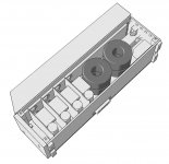
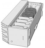
The final product with independent digital PSU and analog PSU is another matter as the digital module has 4 BIBs for the BIII, FIFO, USB-I2S module and accessories so it should get a little hotter.
I redesigned the BIB PCB for this case so i could make the thing more compact...we will see if it's feasible, here is a peak..
The resistor gets hot but a small heatsink takes care of the transistors.
The final product with independent digital PSU and analog PSU is another matter as the digital module has 4 BIBs for the BIII, FIFO, USB-I2S module and accessories so it should get a little hotter.
I redesigned the BIB PCB for this case so i could make the thing more compact...we will see if it's feasible, here is a peak..
Attachments
Last edited:
hmm, seems to me certain elements of the BIII and fifo are analogue... the master XO board from the fifo, the 9018's DVDD L/R and AVCC L/R pins are analogue mechanisms and should be treated as such IMO. the model is looking good though, I see you are taking cues from the firstwatt heatsinks? nice
The final product with independent digital PSU and analog PSU is another matter as the digital module has 4 BIBs for the BIII, FIFO, USB-I2S module and accessories so it should get a little hotter.
I redesigned the BIB PCB for this case so i could make the thing more compact...we will see if it's feasible, here is a peak..
You remind me another BIB for the FIFO.
Your case look like a UPS
is it really worth powering the fifo with shunt regs? I can understand powering the flipflops and clocks with their own dedicated shunts directly, but powering the whole thing with shunts when all the consumers on the fifo board have dedicated IC regs seems like creating a lot of heat for not much benefit.
Hi Ian
I am also planning to use the SalasShuntReg to power the BIII. Just want to confirm my understanding is correct, you use 3 SSRLV to power the 3 trident and each set at 5.25V 100mA output? With such small current, why it generate so many heat (60 deg)???
Because the heatsink is facing down, but the hot air goes up
. I'm gonna add more heatsinks and make them facing up. Hopefully I can get the stable temp around 50C.hmm, seems to me certain elements of the BIII and fifo are analogue... the master XO board from the fifo, the 9018's DVDD L/R and AVCC L/R pins are analogue mechanisms and should be treated as such IMO. the model is looking good though, I see you are taking cues from the firstwatt heatsinks? nice
Actually just using heat sinks from old Barko 2K x 2K screens...i work in air traffic control
is it really worth powering the fifo with shunt regs? I can understand powering the flipflops and clocks with their own dedicated shunts directly, but powering the whole thing with shunts when all the consumers on the fifo board have dedicated IC regs seems like creating a lot of heat for not much benefit.
Probably right thanks for the head's up.
cool, well the sinks look nice enough though, I do like that angled fins look.
do what suits, but yeah I think I would either just use batteries and be done wit it, a basic but quality linear supply, or all out and supply the main board with linear and selected parts with shunts directly. powering the whole board is a bit of current and most of the benefits of shunt regs dont really apply when there is other regs in the way. the low impedance and high bandwidth makes little or no difference and sense/force lines dont have access to the loads. of course do what sounds good to you, but the heat created by a 500-600ma shunt is not insignificant, I would want to make that count.
do what suits, but yeah I think I would either just use batteries and be done wit it, a basic but quality linear supply, or all out and supply the main board with linear and selected parts with shunts directly. powering the whole board is a bit of current and most of the benefits of shunt regs dont really apply when there is other regs in the way. the low impedance and high bandwidth makes little or no difference and sense/force lines dont have access to the loads. of course do what sounds good to you, but the heat created by a 500-600ma shunt is not insignificant, I would want to make that count.
cool, well the sinks look nice enough though, I do like that angled fins look.
do what suits, but yeah I think I would either just use batteries and be done wit it, a basic but quality linear supply, or all out and supply the main board with linear and selected parts with shunts directly. powering the whole board is a bit of current and most of the benefits of shunt regs dont really apply when there is other regs in the way. the low impedance and high bandwidth makes little or no difference and sense/force lines dont have access to the loads. of course do what sounds good to you, but the heat created by a 500-600ma shunt is not insignificant, I would want to make that count.
It is really great that we can have this kind of advice from an expert member like you. This save us lot of time and money. I will try linear PSU or rechargeable battery to power the FIFO.
- Home
- Source & Line
- Digital Line Level
- Asynchronous I2S FIFO project, an ultimate weapon to fight the jitter