with rice though, you are really supposed to submerge the phone in it, there is not enough rice in china to submerge all of my electronic parts hehe.
hey Regal, i found i had some epsom here, ive baked it, went totally opaque white, which seems logical, but when its absorbed its full of water, does it turn back to clear? just some indication of it doing its job would be cool.
sorry for the OT Ian
yea it will get clumpy/clearer when it absobs the water, but it won't turn back into crystals.
Hi Ian,
great project. A couple of questions.
What is the reason you choose to use three PCBs instead of one?
Even if someone doesn't need the SPDIF input, e.g. they want to use USB, the savings on PCB, interconnects etc. are probably in the range of the cost of the SPDIF section anyhow?
In your experience, what is the best performance in terms of jitter that can be achieved using an integrated (single chip or DSP e.g. ADI) ASRC vs your very nice design?
Thanks SunShade, very good questions.
I’m an audiophile, I need more performance, more flexibility, more combination and more try, so I designed this modularized FIFO KIT. However, if I design similar project for consuming market, it would be an all-in-one PCB and could run plug-and-play, just as you mentioned, that’s reasonable.
Actually the FIFO board could work independently from the other two PCB without any problem if you are happy with it. Clock board is just for upgrading the clock performance, while the S/PDIF board is just for expanding DIR and DIT functions.
Later on, I’ll design couple of new clock boards by integrating with different kind of clock solutions. For example, Si570, remarkable low jitter performance (-112db/100Hz, -150db/10MHz) and sounds wonderful, but it need a software based driver to run. Without this upgradeable clock board configuration, we even don’t have chance to play with it.
I2S FIFO is kind of straightforward solution to deal with jitter problem. It just uses a new low jitter clock to replace the old one and do not change anything on the I2S data. The principle is very clear, everybody could understand. ASRC is totally the different story. It uses DSP calculating power to up-sample the input I2S data. AD1896 is a very special case of ASRCs. It employed ‘rate estimator’ to get more accurate up-sampling processing which makes it coming with better jitter attenuation than other ASRC chips. Personally, I’m very interested in it. If I get time, I’d like give it a try to see which one is better.
Have a good nightJ. Ian
[...]The statement above does not disagree with my post. but i would like you to show me a regulator that is effective enough at these high frequencies to not leave all of the heavy lifting to the decoupling caps. Salas himself and those in the thread when i asked about this, brought this up WRT the BJT version. i also stated that low noise is still important and asked how the reg you linked compares to the 9uV LDOs. so where exactly do you disagree?
when i find a regulator with better noise performance over the range of interest (and particularly down in the low frequency 'jitter band') than A123 batteries i'll consider it[...]
Regarding noise, Demians regulator he posted on this thread is magnitudes better than any LDO regulator. Let's look at the ADP151 which is coincidentally specified having 9µV output noise.
You may look at Figure 23 of this Datasheet. 1/f knee is >10kHz!! Noise is somewhere 20nV/rtHz.
Also, the CFP transistors are very fast, I would think even faster than a LDO, if you are concerned about high frequency. But very high frequencies have to be adressed with capacitors anyway.
Also, Werner Ogiers wrote a nice article about regulator and battery noise here. Page 4 may interest you.
This is a really interesting project, and jitter performance of the I2S signals can be very very good and depending to a great deal from the clock. That's why I believe that substituting the LDO regs with something like Demian's reg is almost mandatory, if you want to get out the most from a good clock and from this FIFO buffer achitecture.
[...]I2S FIFO is kind of straightforward solution to deal with jitter problem. It just uses a new low jitter clock to replace the old one and do not change anything on the I2S data. The principle is very clear, everybody could understand. ASRC is totally the different story. It uses DSP calculating power to up-sample the input I2S data. AD1896 is a very special case of ASRCs. It employed ‘rate estimator’ to get more accurate up-sampling processing which makes it coming with better jitter attenuation than other ASRC chips. Personally, I’m very interested in it. If I get time, I’d like give it a try to see which one is better.
I'd put some money on your FIFO compared to an ASRC, being it TI, AD or whatever.
I would think even faster than a LDO, if you are concerned about high frequency. But very high frequencies have to be adressed with capacitors anyway.
just as i said in the first post you replied to, i made it pretty clear i thought very high transient speed was not of huge importance
this decade old article is of no relevance to todays lithium cells, read it years ago.Also, Werner Ogiers wrote a nice article about regulator and battery noise here. Page 4 may interest you
as for the rest, i'm really not interested in talking about it, i posted my caveats regarding my post, mentioned i saved Demian's schematic to try along with other things, but you still want to argue? why is that? can we please just get on with talking about the actual subject at hand? you, just as i are free to use whatever clock and power supply you wish; you will never please everyone
@ Ian:
on the other hand i'm dead keen to try out the Si570 DSPLL, which pwns any other clock ive seen i think and simplifies psu design and layout (as long as good RF technique is used for decoupling) due to only needing 1 clock, thanks for the tip Ian!! it has its own internal regulators and PSRR so large i would challenge you to make any meaningful difference past a competently designed IC reg or battery to supply it.
Last edited:
Why do you think I'm arguing with you?
I only say that an LDO is by far worse at LF than eg Demian's circuit and that this is detrimental for clock performance.
And I thought that you may be interested in reading the article. No need to feel attacked.
Please go forward with whatever you find important.
Ciao.
I only say that an LDO is by far worse at LF than eg Demian's circuit and that this is detrimental for clock performance.
And I thought that you may be interested in reading the article. No need to feel attacked.
Please go forward with whatever you find important.
Ciao.
Si570 + Regulator stuff
The SI570 looks really interesting. However you need to learn how to read datasheets to see the reality. The phase noise numbers and jitter numbers are from a 112 MHz measurement. There is nothing for the range we care about. Also there are no plots. The jitter numbers are more meaningful and the most important for us might be the period jitter of 2 pS rms and 14 pS P-P. DDS solutions usually have spurious outputs and often they are close to the carrier. In some applications they may not matter and they are not usually mentioned when discussing phase noise. Also there is an actual floor below which improving jitter/phase noise will make no difference in a digital system.
If the device is good enough it suggests a simpler solution that the full buffer here- just use it as a PLL locked reclocker following the input frequency. The device has a very wide adjustment +/- 3500 ppm and a source outside of that range would be broken. Taking the basic clock rate info from the line receiver and few latches + some smarts in an fpga + a classic PLL could make a very good reclocking solution. It takes 10 mS to switch to a different frequency so a single Si571 could do the job. Two, programmed at 22.5792 MHz and 24.576 MHz would make it easy and eliminate the need for the reprogramming of the chip. It would need two nominal frequencies selected by the input receiver and a good type 2 PLL to lock quickly and reject short term variations.
As I pointed out elsewhere there is no universal perfect regulator. You will need to make some tradeoffs to get the best solution for a specific application. The circuit I cooked up was targeted specifically at oscillators and getting maximum isolation from the external supplies with low noise. While it seems to work well in other applications its not necessarily the best option if the load is dynamic.
Any amplifier circuit is effectively inductive at its output (the gain falls with frequency so the output Z increases with frequency). As such the output cap becomes more important with frequency.
Making a bypass that is nonresonant and has enough current reserve up to the highest frequency of interest is a challenge and will be a different challenge for each specific application. Every component and trace is an LRC network and most change with voltage and current. Ideally you would measure at the critical pins of the controlled device with a vector network analyzer to see what its impedance is doing across the useful range. This is far from practical. At least think about the problem as a network, not a magic cap.
For the crystal oscillator the current doesn't change ever (unless something is wrong), it is voltage sensitive so voltage needs to be stable and noise free and the ripple current is at the output frequency so its a simple problem. The rest of the digital circuitry in a digital audio device is a much different case.
Also there is an actual floor below which improving jitter/phase noise will make no difference in a digital system.
Agree. The best clock is the sampling clock. However, even you use same clock, you couldn't duplicate each phase exactlly the same. Just think about what clock was using by a studio for recording? Even we use the perfact clock for playback, the sampling jitter is still there, impossible to get rid of, that would be meaningless(except the computer based music, which was generated by software without sampling).
DDS solutions usually have spurious outputs and often they are close to the carrier. In some applications they may not matter and they are not usually mentioned when discussing phase noise.
Si570 is XO based DPLL, not DDS. And Si571 comes with bigger jitter than Si570 (20dB greater on phase noise), I suspect that phase noise was intrduced by the control voltage and the internal ADC.
Ian
The bigger jitter makes sense with the large voltage control range.
The real floor of a digital system comes from the digital process. Below a certain jitter number the end value of a sample won't change. Its limited by the resolution (number of bits) of the system. Subdivide the sample rate by the number of increments and that is where the floor in time lives. There are other details that suggest lower jitter is better but at some point it cannot be resolved.
The real floor of a digital system comes from the digital process. Below a certain jitter number the end value of a sample won't change. Its limited by the resolution (number of bits) of the system. Subdivide the sample rate by the number of increments and that is where the floor in time lives. There are other details that suggest lower jitter is better but at some point it cannot be resolved.
demian, its not true that we dont care about ~112MHz jitter, in fact i chose the number from that range specifically, there are a number of other phase noise measurements as well. to run with sabre which has an internal 1.4MHz clock for the DSP/OSF, the clocks used in 9018 are generally in the range of 80-120MHz
what interests me about it apart from the chameleon qualities, is its high PSRR due to its output stage/buffer and already has onboard regulators. i'd like to see some 50-100Hz phase noise too, but that can wait till we try it out
what interests me about it apart from the chameleon qualities, is its high PSRR due to its output stage/buffer and already has onboard regulators. i'd like to see some 50-100Hz phase noise too, but that can wait till we try it out
Last edited:
Why do you think I'm arguing with you?
I only say that an LDO is by far worse at LF than eg Demian's circuit and that this is detrimental for clock performance.
And I thought that you may be interested in reading the article. No need to feel attacked.
Please go forward with whatever you find important.
Ciao.
sorry man, that was partially me being snippy due to having to pack up my entire workshop in the middle of a time where i'm already a bit behind with orders. however ive lost count the number of times someone has quoted that ancient article to me to show the noise of batteries.
I just dont find it particularly productive talking about the have-nots of the board when the haves have not even been explored yet and you are free to use whatever reg you like.
i'll crack mine open in a few days, after the worst of the rain is over
demian, its not true that we dont care about ~112MHz jitter, in fact i chose the number from that range specifically, there are a number of other phase noise measurements as well. to run with sabre which has an internal 1.4MHz clock for the DSP/OSF, the clocks used in 9018 are generally in the range of 80-120MHz
what interests me about it apart from the chameleon qualities, is its high PSRR due to its output stage/buffer and already has onboard regulators. i'd like to see some 50-100Hz phase noise too, but that can wait till we try it out
I know many customers could not care less about 112mhz jitter with this design? The fifo sort of makes the Sabre 80-120mhz asych (or synch) reclocking a bit redundant? Wouldn't you want to turn off the PLL if you were resorting to using a Sabre with this device? I guess since the filter is integral to the Sabre you still want the reclock to do some cleanup afterwards? But trying to bend this design around a unquie switcher chip may not be the best solution for all. The improvement with this fifo inserted in front of a tda1541 for the typical guy with a cs8412-tda1541a NOS dac is going to be huge, without investing a fortune in the clock. Hopefully the clock choice is flexible so all parties can be happy.
One question I have is what are the frame lengths of the fifo output, is it possiblt to have true 16 and or 24 bit data, or is this sending 32 bits lengths per channel ?
huh?? wut? bend the design? resort to use with sabre? huh? this is talk of the clock module. i'll be using this fifo for the spdif inputs on my sabre. the clock board is completely separate remember, no bending needed apart from harnessing the logic voltage to switch speeds. No bending by Ian is going to happen anyway, the design phase is finished, thats why i've been having a bit of a short fuse with people suggesting changes, when from this point on, the changes are up to you.
i'll be looking at this DSPLL clock unit for use as the master clock on my dac, which is very much multichannel USB focused for my digital crossover and at higher speeds than the fifo can cope with. i will still be using the OS filter, but running sync mode and to get the higher speeds you need to be running something like 96MHz and 88MHz. i may try to work it in so all the inputs have a single master eventually, but thats a bit of work. after initial testing the fifo will probably end up just on Spdif, or and this is possibly a bit more likely, on a dedicated 2 channel headphone rig
i'll be looking at this DSPLL clock unit for use as the master clock on my dac, which is very much multichannel USB focused for my digital crossover and at higher speeds than the fifo can cope with. i will still be using the OS filter, but running sync mode and to get the higher speeds you need to be running something like 96MHz and 88MHz. i may try to work it in so all the inputs have a single master eventually, but thats a bit of work. after initial testing the fifo will probably end up just on Spdif, or and this is possibly a bit more likely, on a dedicated 2 channel headphone rig
Last edited:
no drama Regal, yeah i'm keen to get playing with it, i think its a great concept for traditional 2 channel, it should be pretty much ideal, so it seems a shame to just use it for spdif on a dac where that probably wont get used that often. i'm thinking more and more it will go into a dedicated headphone and small powered monitor rig for the workshop
I was looking at this specific system which is why I indicated that 100 MHz oscillator phase noise would not be indicative of the expected performance. It would be quite possible to use an ESS chip synchronously with this system but you would need to have two oscillators or switch frequency and the possible target frequencies are like 122.88 MHz and 112.896 MHz. I believe there is an upper frequency limit for the ESS in sync mode. You would also need to divide down for the logic in the system to work properly.
Actually it seems their XO modules work in three ranges and the lowest has the highest jitter numbers. The more conventional oscillators actually get better down to 4 MHz and then start to get worse. Given the size of the module the crystal blank must be pretty small so this is very good performance given the size of the crystal.
If I can get my low noise measurement front end working right I will measure some sources, like batteries, to see what I can learn. I need to get the hum sensitivity out of it first.
last off topic post on this. my plan would be to use one clock for the 24x and 22.1x integers and a dedicated 10 or 12MHz clock for logic. there is already code and logic level outs to trigger the change between what is currently 2 discrete TCXOs. it may not end up the be all end all, but definitely worth some investigation. all of the switching and division hardware is already in place, but I would be looking at spinning a dedicated board and maybe liaise with Acko for a firmware update for trying this out.
anyway best get back to the topic at hand, sorry i should have been more specific that i was talking about it being useful for my and others systems more broadly. obviously Ian also sees some potential or he wouldnt have mentioned it in the first place.
i'll be interested in some updated battery noise and impedance vs frequency plots; the datasheets for the A123 are pretty decent and cover all the internal impedance vs temp etc, but i gather they didnt expect them to be used so much in audio so noise is not covered
Last edited:
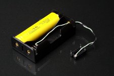
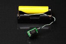
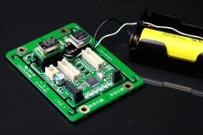
My little toy, A LiFeP04 battery based reference XO power supply
I did a little toy. I connected an A123 LiFeP04 battery to a 14pin IC socket. This configuration works as an adapter bypassing the power of the PCB. So the battery could power the XO oscillator directly from the socket as a reference without changing any other function. The output voltage of LiFeP04 is just around 3.3V. This little toy is really working.
I’m looking for power supply which comes with equal or closing low noise performance than a batter. But I’m not lucky so far. It’s really hard to measure if the PUS output noise is low, especially within wide bandwidth. However, by compare with the battery reference, it’s very easy to tell which one is better. I did some research by making use of this reference, the result was very interesting.
It’s also available that replacing the battery with other PSU to be evaluated.
Attachments
- Home
- Source & Line
- Digital Line Level
- Asynchronous I2S FIFO project, an ultimate weapon to fight the jitter