9uV, is that ADP-151? A shunt reg (like TPA trident or salas) sounds better with XO.
2. Powering two oscillators at same time with 9uV RMS low noise high PSRR LDO and independent EMI suppression filters.
Hi 2A3SET,
Good point. I'd like to give a try. Do you konw who has the PCB of salas shunt regulator, 3.3 or 5V version? Comparing with linear amp, the XO is more like a RF circuit, it even sensitive to the pin inductance of a decoupling capacitor. Ian
Hi Ian,
Quanghao should have the 3.3V version,
http://www.diyaudio.com/forums/quan...t-regulator-v-1-0-dac-more-3.html#post2316375
Or you can try the TPA trident without the CCS,
Trident
So far I have two setup using shunt for XO with good result,
1. swap ADP-151 with Salas shunt on audio-widget for Silab Si532 dual rate XO.
2. bypass "The flea" reg on AckoDAC with Audio-GD shunt (sounds even better than LifePO4 battery).
Hi Ian,
Quanghao should have the 3.3V version,
http://www.diyaudio.com/forums/quan...t-regulator-v-1-0-dac-more-3.html#post2316375
Or you can try the TPA trident without the CCS,
Trident
So far I have two setup using shunt for XO with good result,
1. swap ADP-151 with Salas shunt on audio-widget for Silab Si532 dual rate XO.
2. bypass "The flea" reg on AckoDAC with Audio-GD shunt (sounds even better than LifePO4 battery).
Hi 2A3SET,
Thank you for the links. I'll try to get one. Reagrds,Ian
Hi, Ian
Now I'm on the hard work of ESS9018 parallel 8DACs per channel and when it completed I shall send you asap
Thanks
Anadigit
Thanks Anadigit, How's going? I'm looking forward to that!
Ian
Measuring Jitter
Ian asked me how I measure jitter. It can get pretty involved but here are the basics.
The most useful is probably measuring at the main analog output. This process was documented pretty thoroughly by J Dunn, better than I can do, so I'll concentrate on the essentials of doing it.
You will need the following:
1) Test files (I have pulled some from the web and created some).
2) A way to play them (obvious)
3) A good analog to digital converter that won't limit the measurements. I use an ESI Juli@ card. The host PC can affect things and you will need to do some calibration to be sure of what you are seeing with the system.
4) An FFT capture package. There are free ones but I have not looked too deep. I use Praxis, primarily a speaker package, because it has very versatile and useful tools in it. Its pricey at close to $1,000 but I have got really good value from it.
5) lots of care in the setup since you will be looking a low level noises it helps to have a pretty clean setup.
I make a long file, 5-10 minutes, and do a hi resolution, up to 16,777,216 points and usually 5-6 averages, which can take almost 10 minutes to capture. I will play the test track at 44.1 for example and capture at 192, partly to make sure the two are not synchronous, which could hide things.
The files can be made with various tools, including Audacity. The test tone should be an integer sub-multiple of the sample rate. At 1X sample rates (44.1K and 48K) the tone will be 11,025 or 12,000. At the 2X or 4X rates they can be higher but then they are beyond the audio range and even some dacs that handle those rates will attenuate or even remove them.
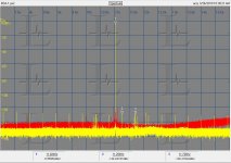
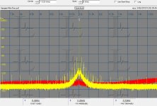
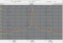
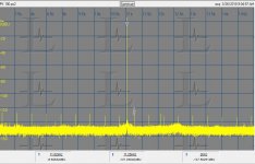
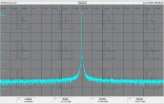
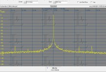
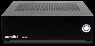
I have attached three representative captures to illustrate what you will see. First is a Bryston BDA-1, which is really very good. You can see the textbook Jtest pattern. The second is the Apogee Minidac, which shows much higher jitter and especially the broadband jitter close to the "carrier". That is similar to the noise plot of a fair crystal oscillator. Finally is a real close in measurement of the Bryston. It has 10Hz span so each division is about 1 Hz. You can see two symmetrical blips at 2.5 Hz from the carrier. At this resolution I can not be sure if they are from the dac or the measurement system. The last two plots are an Auraliti PK100 analog output which looks a little different. The first plot is the same 8 KHz span as stereophile uses for these tests, the second is a zoomed version showing the close in phase noise, what my homework has been for the last year.
I'll be happy to post the test files if they will fit here.
Ian asked me how I measure jitter. It can get pretty involved but here are the basics.
The most useful is probably measuring at the main analog output. This process was documented pretty thoroughly by J Dunn, better than I can do, so I'll concentrate on the essentials of doing it.
You will need the following:
1) Test files (I have pulled some from the web and created some).
2) A way to play them (obvious)
3) A good analog to digital converter that won't limit the measurements. I use an ESI Juli@ card. The host PC can affect things and you will need to do some calibration to be sure of what you are seeing with the system.
4) An FFT capture package. There are free ones but I have not looked too deep. I use Praxis, primarily a speaker package, because it has very versatile and useful tools in it. Its pricey at close to $1,000 but I have got really good value from it.
5) lots of care in the setup since you will be looking a low level noises it helps to have a pretty clean setup.
I make a long file, 5-10 minutes, and do a hi resolution, up to 16,777,216 points and usually 5-6 averages, which can take almost 10 minutes to capture. I will play the test track at 44.1 for example and capture at 192, partly to make sure the two are not synchronous, which could hide things.
The files can be made with various tools, including Audacity. The test tone should be an integer sub-multiple of the sample rate. At 1X sample rates (44.1K and 48K) the tone will be 11,025 or 12,000. At the 2X or 4X rates they can be higher but then they are beyond the audio range and even some dacs that handle those rates will attenuate or even remove them.
I have attached three representative captures to illustrate what you will see. First is a Bryston BDA-1, which is really very good. You can see the textbook Jtest pattern. The second is the Apogee Minidac, which shows much higher jitter and especially the broadband jitter close to the "carrier". That is similar to the noise plot of a fair crystal oscillator. Finally is a real close in measurement of the Bryston. It has 10Hz span so each division is about 1 Hz. You can see two symmetrical blips at 2.5 Hz from the carrier. At this resolution I can not be sure if they are from the dac or the measurement system. The last two plots are an Auraliti PK100 analog output which looks a little different. The first plot is the same 8 KHz span as stereophile uses for these tests, the second is a zoomed version showing the close in phase noise, what my homework has been for the last year.
I'll be happy to post the test files if they will fit here.
Attachments
Ian asked me how I measure jitter. It can get pretty involved but here are the basics.
The most useful is probably measuring at the main analog I'll be happy to post the test files if they will fit here.
Thanks Demian,
You did great job! Very smart idea, I like it. I'm reading your post right now. It seems I need set up same system to follow up your test.
") Ian
Ian
Last edited:
3) A good analog to digital converter that won't limit the measurements. I use an ESI Juli@ card. The host PC can affect things and you will need to do some calibration to be sure of what you are seeing with the system.
Hi Demian,
I have a couple of questions about the sound card:
1. How do you deal with the A/D sampling jitter from the clock of the sound card?
2. Usually the EMI noise from the PC switching PS is terrible. Is that the USB sound card with external PS any better than the PCI card doing this kind of measurment job?
Thanks, Ian
What you get the the additive composite of the source and the sound card. I lucked out using the Juli card since it has a pretty low residual jitter. I have tried other cards. The USB capture cards I have tried are poor for some reason. They are the EMU 0202 and the Maudio transit. Lots of noise and capture issues that may be resolvable but more work with no certain end. I have also tried an RME card that seems to have its own plan for capture and prevented me from getting good data even on a digital loopback. Again, possibly resolvable, but I don't have the time to wade into it.
For jitter measurements the important part is to look for the symmetrical sidebands. Everything else is simply noise in the pickup. Calibrating the system is important so you can separate the signals. You need several clean sources since none will be as clean as you would like. An analog oscillator may have a pretty low noise floor but a higher residual phase noise and less frequency stability. A crystal controlled source may have other junk but a pretty clean tone. My Boonton 1121 has a crystal stabilized analog oscillator, which should be really good, but shows the PLL effects of wandering pretty easily on these tests. No easy answers. The system and its grounding are also a big issues but careful setup and possibly isolation in the right places will reduce the issue a lot. This is more like FCC testing in that you will need to know the sources of what you see and can ignore those you know to not be from your DUT.
The host PC has changed since the first captures, with a new motherboard (MSI AMD AT MB) and power supply.
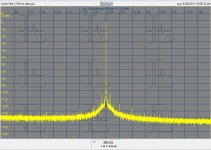
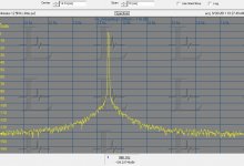
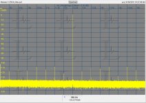
I just did a "quick" test with a Minirator crystal controlled battery powered generator and a Krohn Hite KH4400 low distortion oscillator (ac powered) to show the basic cal process. neither of these are really low enough as a source to be without fault. For that I use a Wenzel 10 MHZ oscillator divided down to 10 KHz. That division yields a really low noise floor, much lower than nay ADC or DAC but its a PITA to setup. I need to build it into a standard test fixture when time permits.
The Minirator in the first two captures was done with the 16M point fft. The KH4400 in the following two could not be measured that way. Its frequency stability is not good enough so the center frequency moves bins and is averaged out. The measurement is a 500K point FFT.
If time permits I will set up the original cal stuff but I'm scrambling to get ready for Burning Amp tomorrow.
For jitter measurements the important part is to look for the symmetrical sidebands. Everything else is simply noise in the pickup. Calibrating the system is important so you can separate the signals. You need several clean sources since none will be as clean as you would like. An analog oscillator may have a pretty low noise floor but a higher residual phase noise and less frequency stability. A crystal controlled source may have other junk but a pretty clean tone. My Boonton 1121 has a crystal stabilized analog oscillator, which should be really good, but shows the PLL effects of wandering pretty easily on these tests. No easy answers. The system and its grounding are also a big issues but careful setup and possibly isolation in the right places will reduce the issue a lot. This is more like FCC testing in that you will need to know the sources of what you see and can ignore those you know to not be from your DUT.
The host PC has changed since the first captures, with a new motherboard (MSI AMD AT MB) and power supply.
I just did a "quick" test with a Minirator crystal controlled battery powered generator and a Krohn Hite KH4400 low distortion oscillator (ac powered) to show the basic cal process. neither of these are really low enough as a source to be without fault. For that I use a Wenzel 10 MHZ oscillator divided down to 10 KHz. That division yields a really low noise floor, much lower than nay ADC or DAC but its a PITA to setup. I need to build it into a standard test fixture when time permits.
The Minirator in the first two captures was done with the 16M point fft. The KH4400 in the following two could not be measured that way. Its frequency stability is not good enough so the center frequency moves bins and is averaged out. The measurement is a 500K point FFT.
If time permits I will set up the original cal stuff but I'm scrambling to get ready for Burning Amp tomorrow.
Attachments
If time permits I will set up the original cal stuff but I'm scrambling to get ready for Burning Amp tomorrow.
I'm gonna try to get one of that sound card. Is that Juli@, right? Everything connected to jitter is not easy
.Enjoy the Burning Amp, have a good time.
Ian
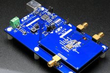
I will be testing the TI demo board for their best ADC chip. It looks to be quite well done. I'll patch it through the Juli@ card.
The RME card I have seems to have a dsp that wants to touch the digital input for some reason. And its mixer may be changing levels etc. Not sure how to move that all aside.
The software looks really interesting. Do you have a cross correlation for the FFT? Here are some references into how its used for phase noise measurement. http://www.holzworth.com/Aux_docs/Holz_MWJ_TechFeat_Feb2011.pdf http://www.amlj.com/files/products%20page/phasenoise-technique.pdf I can find more but you should be able to get the basic idea.
I have some questions on this measurement method.
I'd be very happy if any of you could give me answers.
Is the method adequate to characterize Ian's board?
According to ESI's web page, the dynamic range of 24-bit/192kHz ADC is 114dB. Your measurement results show those noise floors are approximately between -140 dB and -150 dB. Can we regard the noise floor values obtained are reasonable?
My last concern is that the method is not sensitive enough to Ian's project.
I'd be very happy if any of you could give me answers.
I understand that this method is originally designed to measure a jitter inherent in S/PDIF interface by employing the worst case binary pattern in the test signal. Ian's project does not involve S/PDIF interface. His input and output signals are I2S. Moreover, the Julian Dunn method requires a combination of both transport and DAC. The performance of transport and DAC may affect the result very much.The most useful is probably measuring at the main analog output. This process was documented pretty thoroughly by J Dunn, ...
Is the method adequate to characterize Ian's board?
3) A good analog to digital converter that won't limit the measurements. I use an ESI Juli@ card. The host PC can affect things and you will need to do some calibration to be sure of what you are seeing with the system.
According to ESI's web page, the dynamic range of 24-bit/192kHz ADC is 114dB. Your measurement results show those noise floors are approximately between -140 dB and -150 dB. Can we regard the noise floor values obtained are reasonable?
My last concern is that the method is not sensitive enough to Ian's project.
I will be testing the TI demo board for their best ADC chip. It looks to be quite well done. I'll patch it through the Juli@ card.
The RME card I have seems to have a dsp that wants to touch the digital input for some reason. And its mixer may be changing levels etc. Not sure how to move that all aside.
The software looks really interesting. Do you have a cross correlation for the FFT? Here are some references into how its used for phase noise measurement. http://www.holzworth.com/Aux_docs/Holz_MWJ_TechFeat_Feb2011.pdf http://www.amlj.com/files/products%20page/phasenoise-technique.pdf I can find more but you should be able to get the basic idea.
Hi,
thank you for the cross-correlation links! I am currently investigation on this. My current finding is, if you use only 1024 FFT you will have this noise figures and averaging will not help that much. The thing changes dramatically if you use a 65k FFT. With my test currently on my web, I used a 2^25 FFT. Any way, you may not go below to the theoretic the noise floor of a given ADC (16 bit about -144; 24bit about -180 db).
Hp
I understand that this method is originally designed to measure a jitter inherent in S/PDIF interface by employing the worst case binary pattern in the test signal. Ian's project does not involve S/PDIF interface. His input and output signals are I2S. Moreover, the Julian Dunn method requires a combination of both transport and DAC. The performance of transport and DAC may affect the result very much.
Is the method adequate to characterize Ian's board?
Prism has demonstrated that this is a good method for looking at all sources of jitter. The fundamentals are valid for measuring very low levels of jitter, down to the limits of the DAC used. However you need to validate and calibrate the measurements to know where the limits are.
According to ESI's web page, the dynamic range of 24-bit/192kHz ADC is 114dB. Your measurement results show those noise floors are approximately between -140 dB and -150 dB. Can we regard the noise floor values obtained are reasonable?
Noise is much more complicated an issue than a single number. The dynamic range number needs to reflect the bandwidth used. A narrower bandwidth in the measurement will result in a lower noise to the limits of the system. The ultra high resolution FFT's have "bandwidths" in the fractional Hertz range. There is very little energy in the small piece that is being measured, which is why the numbers are so low.
My last concern is that the method is not sensitive enough to Ian's project.
Again its not that simple. Even if Ian's project ends with femtosecond resolution, if no DAC can realize that jitter it really doesn't matter. What will matter is getting the really low jitter through the dac to the analog domain. Its also easier to measure there.
Measuring really low jitter on the clocks otherwise requires a reference oscillator (difficult to obtain and expensive) a low noise RF mixer, some other rf and baseband bits and pieces and a good FFT. Its also very sensitive to setup since you are looking for noise as much as 170 dB below the carrier level. Many external things will degrade the measurements. I tried it with a pair of Wenzel oscillators and even reorienting them on the bench made a difference. Its also possible to see the effect of gravity on the crystal with that setup.
The important issue is whether the goal is a number or are you measuring for diagnostic reasons? I have found the method used above useful for finding problems and improving the system performance. The pictures show that you can see meaningful differences between devices that are very good. Upgrades for the oscillator and power supply of the Juli@ card will probably help. My pending experiments with the TI board should shed some light on where the limits are in this process.
Hi,
thank you for the cross-correlation links! I am currently investigation on this. My current finding is, if you use only 1024 FFT you will have this noise figures and averaging will not help that much. The thing changes dramatically if you use a 65k FFT. With my test currently on my web, I used a 2^25 FFT. Any way, you may not go below to the theoretic the noise floor of a given ADC (16 bit about -144; 24bit about -180 db).
Hp
The cross correlation is a trick for removing the reference oscillators noise contribution. If the noise component in both mixer outputs has a common element the correlation will leave that as it removes the non-correlated part. The method usually requires two separate reference oscillators which will have different instantaneous noise. The common noise comes from the DUT and will remain as the non-correlated noise goes away. I agree an 1024 point fft is not enough but the preprocessing of the signal reduces the demands on the fft step.
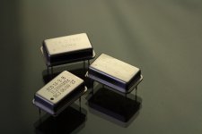
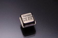
Collections of oscillators and XOs
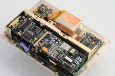
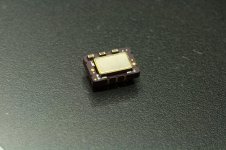
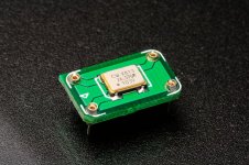
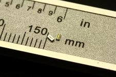
I collected quite a few oscillators and XOs so far. I just post some pictures of them.
I look for not only the clocks with good expected low jitter performance, but also normal clocks and clock solutions. Since now I have the FIFO platform, I could feel the ‘pure’ clock with particular jitter parameters, rather than the combination of jitter accumulation of PLL of SPDIF receiver (secondary pll for some applications), the SPDIF transmission and the source clock.
I just want to feel different clocks, as well as how and how much in difference between good and normal.
The collection is still going on. Some of them still under waiting for the back order delivery. It will take me some time to go through all of them. However, how to get the right evaluation is a question.
Ian
Attachments
-
 EF5680A2.JPG434.4 KB · Views: 1,567
 -
 D75F.jpg131.3 KB · Views: 1,592
 -
 CWX813.jpg169.3 KB · Views: 1,619
 -
 JitterCleaningClock.JPG606.3 KB · Views: 1,581
 -
 CCHD957_24.5760.JPG96.4 KB · Views: 1,532
 -
 PLL1708.jpg143.7 KB · Views: 693
 -
 NZ2520SD.JPG279.3 KB · Views: 622
 -
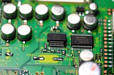
 NormalClk.JPG245.5 KB · Views: 668
 -
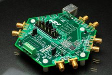
 SilabsEVB.JPG562.8 KB · Views: 729
 -
 TentClk.JPG268.1 KB · Views: 694
Ian asked me how I measure jitter. It can get pretty involved but here are the basics.
The last two plots are an Auraliti PK100 analog output which looks a little different. The first plot is the same 8 KHz span as stereophile uses for these tests, the second is a zoomed version showing the close in phase noise, what my homework has been for the last year.
Is this your homework for last year? You did good job Demian! And you are drawing my interesting.
Ian
Attachments
Sine to square converter for rubidium clock FE-5680A
I still couldn’t give up my FE-5680. I suspect the sine to square converter was one of the problems.
I don’t like the AC coupled 74XX04(14) sine to square converter. Because additive jitter introduced by both TTL/CMOS buffer and the feedback from its output.
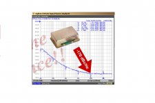
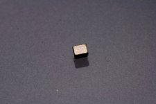
I found a very nice low phase noise clock fanout buffer for sine to LVTTL clock convertion, CDC3RL02, with only –149 dBc/Hz at 10-kHz Offset Phase Noise , or – 0.37-ps (RMS) Output Jitter. It seems perfect for buffering the rubidium clock output. However, when I got the samples, I was surprised. It’s not a normal concept IC, it’s just a wafer DIE with some BGA underneath. I have no any idea about it although I’m quite confident with my hand SMT skill.
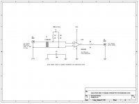
Another idea is LVDS buffer. LVDS usually has much higher speed and less additive jitter comparing to the LVTTL buffer. But I have to convert the un-balanced rubidium clock (from a 50 ohm coaxial cable) into a balanced clock, balun is the solution(two grounds could be isolated as well). Then, feed the differential clock into 65LVDS2(or FIN1002) with 1/2 Vcc bias. I attached the schematics just for reference. I built the circuit on a small PCB. It works fine. The output waveform looks good. I’ll use it for the rubidium clock listening test later on.
High speed comparator is an alternative option. But I don’t know which one is better.
Ian
I did try this rubidium clock on my CD transport but the result was not as good as I thought. Sine to square converter was another issue. Of course it has perfect frequency stability, but it dosn't mean the low jitter perfermance. It seems the actual performance was not as good as the phase noise plot from the FE-5680 PDF file. I don't know why.
I still couldn’t give up my FE-5680. I suspect the sine to square converter was one of the problems.
I don’t like the AC coupled 74XX04(14) sine to square converter. Because additive jitter introduced by both TTL/CMOS buffer and the feedback from its output.
I found a very nice low phase noise clock fanout buffer for sine to LVTTL clock convertion, CDC3RL02, with only –149 dBc/Hz at 10-kHz Offset Phase Noise , or – 0.37-ps (RMS) Output Jitter. It seems perfect for buffering the rubidium clock output. However, when I got the samples, I was surprised. It’s not a normal concept IC, it’s just a wafer DIE with some BGA underneath. I have no any idea about it although I’m quite confident with my hand SMT skill.
Another idea is LVDS buffer. LVDS usually has much higher speed and less additive jitter comparing to the LVTTL buffer. But I have to convert the un-balanced rubidium clock (from a 50 ohm coaxial cable) into a balanced clock, balun is the solution(two grounds could be isolated as well). Then, feed the differential clock into 65LVDS2(or FIN1002) with 1/2 Vcc bias. I attached the schematics just for reference. I built the circuit on a small PCB. It works fine. The output waveform looks good. I’ll use it for the rubidium clock listening test later on.
High speed comparator is an alternative option. But I don’t know which one is better.
Ian
Attachments
Your problem isn't additive jitter. Rubidiums are not going to easily generate audio clock frequencies and they will have significant spurs that may be ignored or hidden the plots. Here is a very good one with info on how they work: PRS10 - Rubidium Frequency Standard If you look into DDS's e.g: AD9912.pdf you will see that they don't have the same performance for every frequency and they can have some "ugly" output frequencies. This is the chip FEI uses in some of their Rubidiums: AD9830 you will see that there are a lot spurs in its output. It turns out that FEI uses a filter on the output to rediuce the spurs. You could build a crystal oscillator at the target frequency and lock it to the Rubidium's output to clean it up, but I would question whether the improved stability will contribute to better sound and the extra power supplies etc. can only degrade the sound.
Here is some info on working with a Rubidium http://www.vk3um.com/Reference%20Data/Reference%20Locking%20the%20IC-910.pdf
For converting the output Wenzel has some good suggestions: Oscillator Waveform Conversion
Here is some info on working with a Rubidium http://www.vk3um.com/Reference%20Data/Reference%20Locking%20the%20IC-910.pdf
For converting the output Wenzel has some good suggestions: Oscillator Waveform Conversion
11.2896000MHz rubidium clock FE-5680A listening test result
I did some listening test on my FE-5680A rubidium clock. And now, I think I have to accept your point.
The FE-5680A and the sine square convertor were powered by two battery packages separately to avoid PSU noise and other issues. The LVDS wave convertor was working very well, much better than the AC coupled 74HCU04 I used before.
Actually the sound of FE-5680A was pretty controversial. It was quite musical and the low range (bass) was very good. The details were not bad as well. But if you listen to it with careful, the problems were obviously there, the bad stereo imaging and the strange 3D feeling. Comparing with the reference clock, the background was not that clean and the sound was bit louder and nosier. It looks like that this rubidium clock has some remarkable features, but at the same time, also something far from perfect. I suspect, just as you pointed out, it might caused by some "ugly" output frequencies which shows as some the spurs on the phase noise plot.
I will remove this FE-5680A from my testing list and do not waste my time on it any more. Some new generation rubidium clock or rubidium based clock solution might be suitable for the audio application, but not include this one.
Rubidiums are not going to easily generate audio clock frequencies and they will have significant spurs that may be ignored or hidden the plots. If you look into DDS's e.g: AD9912.pdf you will see that they don't have the same performance for every frequency and they can have some "ugly" output frequencies. This is the chip FEI uses in some of their Rubidiums: AD9830 you will see that there are a lot spurs in its output. It turns out that FEI uses a filter on the output to rediuce the spurs. You could build a crystal oscillator at the target frequency and lock it to the Rubidium's output to clean it up, but I would question whether the improved stability will contribute to better sound and the extra power supplies etc. can only degrade the sound.
I did some listening test on my FE-5680A rubidium clock. And now, I think I have to accept your point.
The FE-5680A and the sine square convertor were powered by two battery packages separately to avoid PSU noise and other issues. The LVDS wave convertor was working very well, much better than the AC coupled 74HCU04 I used before.
Actually the sound of FE-5680A was pretty controversial. It was quite musical and the low range (bass) was very good. The details were not bad as well. But if you listen to it with careful, the problems were obviously there, the bad stereo imaging and the strange 3D feeling. Comparing with the reference clock, the background was not that clean and the sound was bit louder and nosier. It looks like that this rubidium clock has some remarkable features, but at the same time, also something far from perfect. I suspect, just as you pointed out, it might caused by some "ugly" output frequencies which shows as some the spurs on the phase noise plot.
I will remove this FE-5680A from my testing list and do not waste my time on it any more. Some new generation rubidium clock or rubidium based clock solution might be suitable for the audio application, but not include this one.
- Home
- Source & Line
- Digital Line Level
- Asynchronous I2S FIFO project, an ultimate weapon to fight the jitter