Ian!
I sit here and enjoy the best sound I have ever had in my system. It improved even more after I took the leap and robbed my aTV from it's Toslink cable, exchanged the connection between the SB and your fifo. The cable change was inspired from one of your pictures of your DAC setup and it makes perfect sense with the fifo. I'm still on 44,1 and s/pdif but I have to say my system sounds lovely.
I just played Chopin, Krystian Zimerman – 4 Balladen • Barcarolle • Fantasie (DG 00289 477 9198)...
thanks and hats off Ian!
/
Thanks TNT for your good news. Both your ears and my scope support your feelings
") .
.Enjoy and explore more.
Ian
SPDIF board out?
Hi Ian,
About everything is working fine. What NOT for heavens sake than?
Its the Ians Fifo-Out! I get no signal whatever I try to record from its output.
I tried a lot of things that came up, but I ran out of ideas.
Te thought that has left, is maybe feeding the USB-card from
the I2S backdoor ?
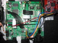
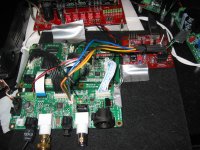
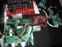
I included some pictures.
Somebody can advise?
Ed
Hi Ian,
About everything is working fine. What NOT for heavens sake than?
Its the Ians Fifo-Out! I get no signal whatever I try to record from its output.
I tried a lot of things that came up, but I ran out of ideas.
Te thought that has left, is maybe feeding the USB-card from
the I2S backdoor ?
I included some pictures.
Somebody can advise?
Ed
Attachments
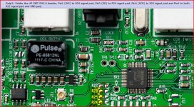
1, Connect J14 on the FIFO Board and J10 on the S/PDIF board with the 10 pin FFC/FPC cable, the connectors are double contacts, so the cable could be either faced up or faced down
aside from your problem, you really should make some attempt to use the ground on the u.fl cables, as it is (not even using the single GND he provided on the dac, just one for all the connections to share is bad enough) they are aerials.. big time. as you have them there you would almost be better off just using ribbon cables.
like that the return currents from the i2s signals are having to find some way back through either a shared power supply ground, or perhaps a ground on that ribbon cable from the dac to waveIO and back through the i2s backdoor to the fifo, across the ribbon to the fifo and another ribbon to the clock board....
also the fifo input is being reclocked again by the onboard flip-flops on the dac board?
as for the problem, it could indeed be the backdoor interfering, I havent tried this combination, i'm not using the spdif out; but that wouldnt be beyond the realms of possibility. Can you test by disconnecting the waveIO and trying to loop through with one of the spdif inputs and spdif output, without the backdoor in place?
Last edited:
Hi Qusp,
Thanks for your sharp attention.
As for the grounding, I had the same remark from Doede, The grounding is done by each Ufl coax directly next to the signal connection.(just with the same Ufl connector) On first sight it is difficult to see, but the grounding really is okay.
I am thinking about the backdoor because of the resitor bridges I had to remove.
I love an output which makes me possible to do instant recording on my HD.
I will disconnect the WaveIO and make a loop. Let you know what happens. Unfortunately I did not try the outputs before the backdoormod! When I try recording I yust hear irregalar ticks, no sign of music signal.
And thank you TNT for your suggestion. I was shure I had the cable right but dit change it for safety sake for an other one. But no succes.
Thanks for the help so far, Ed
Hi Qusp,
Disconnected the WaveIO, fed toslink with a signal, looped coax in-and output.
Nada! Checked the boards for loose contacts/parts but Ian did a too good job on them.
Could not find irregularities of course.
Make myself a litlle but very aromatic Espresso! (That's about the only thing I am good at!)
Thanks for now,
Ed
.
Ed, do the spdif card, the fifo and the clock board work s/pdif -> s/pidf with your dac disconnected?
Like the picture in the end of the s/pdif Manual? Just to maybe isolate the problem...
Sorry for my cable suggestion, it was the only obvious difference i saw comparing my setup.. but I never checked the actual cable I must admit.
/
Like the picture in the end of the s/pdif Manual? Just to maybe isolate the problem...
Sorry for my cable suggestion, it was the only obvious difference i saw comparing my setup.. but I never checked the actual cable I must admit.
/
Hi Ian,
About everything is working fine. What NOT for heavens sake than?
Its the Ians Fifo-Out! I get no signal whatever I try to record from its output.
I tried a lot of things that came up, but I ran out of ideas.
Te thought that has left, is maybe feeding the USB-card from
the I2S backdoor ?
I included some pictures.
Somebody can advise?
Ed
1, If you don't use the spdif output function for now, please disconnect the MCLK and I2S output cable to the spdif board.
2, Replace the dual xo clock board with the standard single clock board and play 44.1K, to see if everything is OK.
Good luck
Ian
Hi Qusp,
Thanks for your sharp attention.
I am thinking about the backdoor because of the resitor bridges I had to remove.
Ed
I had the same problem before, did you short one of the pin to ground (R24 if my memory correct)? this was the step I did not realize and caused no output.
you need to be more specific, quoting a random new years greeting made by someone else is not giving very good context for your question. for example the LFCSP package of the ADP151 has pin 4 as the enable pin.
but i'm not sure which ADP151 you are referring to. also I believe Ian allowed for the alternative use of TPS series regs on some boards
Thanks qusp
.Hi Ian,
Why are you putting .1uF ceramic capacitor between an unconnected (pin4) pin of ADP151 and ground?
Kind regards,
Mihai
qusp gave correct answer. That cap was reserved for other LDOs such as TPS79333 or TPS79933
. Just keep it open for ADP151.Rember? my boss may change his mind on BOM at last minute
.Ian
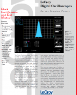
At this performance level the options for measuring jitter are limited. You can spend a bundle on one of the fancy measuring systems and that makes sense if you need to measure a variety of different sources. However for specific sources you can get very good results using a reference oscillator and a double balanced mixer. If you need to go well below the noise of your reference oscillator there are techniques using two reference oscillators and correlation to extract the phase noise that is common. More here: Techniques for Measuring Phase Noise . Phase noise above the sample rate won't affect the output because its conversion is above the system bandpass. This makes it harder to convert from the cycle to cycle measurements (with an effective bandwidth of 1/2 the sample rate I think) to the final audio output.
You can get a Wavecrest with a 2 pS noise floor, and for less that $700. But it still won't tell you what you want to know as well as either the above method or looking at the output of the dac, which is what matters. Looking at the raw clock is a good analytic tool for seeing how much it has been degraded. The phase noise measurements are the best way to make the measurements.
Main Page has added the ability to make the cross correlation measurement using a sound card. You still need two reference oscillators and double balanced mixers. You can get a noise floor of -170 dBC with care. The minicircuits mixers are certainly good enough to start with. The Crystek oscillators may be good enough but you really need a voltage control input to phase lock the oscillators.
Thanks Demian,
I know there is limitation measuring jitter in time domain. But it would be much more difficult in frequency domain. I'll go through the link to see if I could. BTW, do you have any recommendation on mixers for this kind of audio f XO measurement?
Regards,
Ian
a double balanced mixer like this
WJ WATKINS JOHNSON RF Mixer M1A DC-1000 MHz 7dBm SMA | eBay
an audio spectrum analyzer
a low noise preamplifier like in the Wenzel document (not be necessary if the analyzer noise floor is sufficiently low)
a reference oscillator (like the HCD661 OCXO)
WJ WATKINS JOHNSON RF Mixer M1A DC-1000 MHz 7dBm SMA | eBay
an audio spectrum analyzer
a low noise preamplifier like in the Wenzel document (not be necessary if the analyzer noise floor is sufficiently low)
a reference oscillator (like the HCD661 OCXO)
Hi Ian!
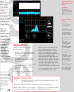
First you measures period jitter not phase, correct you post.
To measure with better accuracy and lower minimum jitter values with you lecroy osc (because of not perfect timing for interliving adc, amplitude-time distirtion conversion etc.) you need to
1. Apply ERES (3bit) function
2. Apply SinX interpolation before eres function if you sampling rate is lower than 4Gs
3. You signal must have maximim amplitude, just before clipping of ADC, use variable attenuator of you scope to maximize signal level.
4. Rise time of you signal should be 3-4ns for lowest osc jitter
regards, Nazar
Thanks Nazar for finding my typing mistake, already have them corrected.
1. Apply ERES (3bit) function -- could you give a bit more details?
2. Apply SinX interpolation before eres function if you sampling rate is lower than 4Gs -- mine already at 8GS/s
3. You signal must have maximim amplitude, just before clipping of ADC, use variable attenuator of you scope to maximize signal level. --- Yes it is, you are right. Did this way
4. Rise time of you signal should be 3-4ns for lowest osc jitter -- Now is around 0.9ns, too small?
What you need for more accuracy with you scope i describe in previous post. High bandwidth is not needed for jitter measurement (for audio equipment) at all.
PS And wm8804 MCLK output not designet to work on 50ohm load.
I think you mean rise time of a scope is more important than the bandwidth on jitter measurement. But usually those two numbers are linked. Have you ever try the result reducing the bandwidth from 1GHz to 200MHz for a same jitter measurment?
I'm not happy with the WM8805 result. That result was measured after I powered it by a battery. It was even worse when I use ac power. Do your mean the MCLK driver of the WM8805 is not good enough? What is the most optimized output impedance it was designed to drive into? I have a 1.8pf active probe, I can measure the 8805 output without load.
I attached the docs of jitter measure package I'm using right now. Please let me know for any suggestion on my jitter testing. Just hope there still be some space to get improve.
Regards,
Ian
Attachments
Last edited:
Fifo output
Hi Ian,
Thanks for your advice of checking!
I can use all inputs, normaly spoken, with a terrific good SQ. So playing music does not give any problem. It is my missing of the possibility to record from the Fifo....
With the single board and 44.1 khz, using the WaveIO via backdoor, output sends rather continuous static, about max level.
These are the findings so far.
!!!!
I must add, that the static ticks occur continuously at the (coax)output even when no input is connected to the SPIDF board , not even the backdoor!
Ed
1, If you don't use the spdif output function for
2, Replace the dual xo clock board with the standard single clock board and play 44.1K, to see if everything is OK.
Good luck
Ian
Hi Ian,
Thanks for your advice of checking!
I can use all inputs, normaly spoken, with a terrific good SQ. So playing music does not give any problem. It is my missing of the possibility to record from the Fifo....
With the single board and 44.1 khz, using the WaveIO via backdoor, output sends rather continuous static, about max level.
These are the findings so far.
!!!!
I must add, that the static ticks occur continuously at the (coax)output even when no input is connected to the SPIDF board , not even the backdoor!
Ed
Last edited:
I had the same problem before, did you short one of the pin to ground (R24 if my memory correct)? this was the step I did not realize and caused no output.
Yes, this step was and is still not very clear to me to. I remember I questionned it it the forum.
What I did, I used a small piece of wire to short pin4 to the nearby groundplane, while connecting it to the signaltrack as well. I am though not shure I did the right thing here. Maybe I should try and cut that wire and see(hear) what happens.
Ed
Hi Ian,
Thanks for your advice of checking!
I can use all inputs, normaly spoken, with a terrific good SQ. So playing music does not give any problem. It is my missing of the possibility to record from the Fifo....
With the single board and 44.1 khz, using the WaveIO via backdoor, output sends rather continuous static, about max level.
These are the findings so far.
!!!!
I must add, that the static ticks occur continuously at the (coax)output even when no input is connected to the SPIDF board , not even the backdoor!
Ed
Sorry, still did get your problem. You mean the coaxial output of the s/pdif board has problem?
Ian
Ian, I believe Demian was recommending the minicircuits frequency mixers
Sorry, still did get your problem. You mean the coaxial output of the s/pdif board has problem?
Ian
Yes, Ian. I don't get output from the (BNC chassispart) output on the S/PDIF board. Just static.
Thanks for your suggestions.
Ed
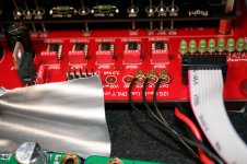
backdoor
Hi Ian/Bigpandahk
Not succesfull until now. I took the backdoor-connector from the board to check it. Found no problem and reconnected it. In the picture I show you how I did that. It is the manual from Ian himself. I show you how I bridged the ground- and the signalpads on the R22 position.
Ed
I had the same problem before, did you short one of the pin to ground (R24 if my memory correct)? this was the step I did not realize and caused no output.
Hi Ian/Bigpandahk
Not succesfull until now. I took the backdoor-connector from the board to check it. Found no problem and reconnected it. In the picture I show you how I did that. It is the manual from Ian himself. I show you how I bridged the ground- and the signalpads on the R22 position.
Ed
Attachments
- Home
- Source & Line
- Digital Line Level
- Asynchronous I2S FIFO project, an ultimate weapon to fight the jitter