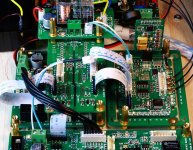
Since we're discussing layout, Ian I notice that you use a separated copper section on each mounting point, is there a reason for this?
Cheers,
Chris
Chris
Oh, That's not a special issue, just for eliminating the possible loop, otherwise the surrounding EMI noise will generate current within as an antenna. Actually all the mounting holes should be connected to the metal case to keep the noise as low as possible, and not to be 'island' at same time.
Ian
Thanks Ian ")
I know its not a particularly critical issue for the device's performance, I just was curious to learn the reasoning, because like you say they're each attached to the enclosure and it was just something that I hadn't noticed before. It seemed as though you'd gone out of your way to do it intentionally so I thought I'd ask since your designs tend to not do things without a good reason!
Chris
Thanks Ian
I know its not a particularly critical issue for the device's performance, I just was curious to learn the reasoning, because like you say they're each attached to the enclosure and it was just something that I hadn't noticed before. It seemed as though you'd gone out of your way to do it intentionally so I thought I'd ask since your designs tend to not do things without a good reason!
Chris
Yes, that right. If not be connected to the GND of the case, the coppers will become islands, for high frequency, that even worth then nothing
.Ian
Ordering parts for the TPS7A4700 boards; What should I order for D1 (LED)? R9 can be pretty much any 1K 1206, right? Thanks in advance for your help
MisterRogers
For TPS7A4700 reg PCB, package of both LED D1 and R9 is 0603.
Yes for red yellow or green, R9 can be 1K with 3.3V output. But if you want blue or white LEDs, you have to make sure the Vf is less than 3V, and R9 may also be reduced.
Anyway, D1 and R9 are just for power indication. You can keep them un-assembled if you don’t need them
.Ian
Greetings,
I finaly tried out the isloator board but I cannot seem to have a lock on the input.
I verified shorts on the resistor array and they checked out good with no shorts.
I don't know where to go from here.
any help appreciated.
thanks
Please confirm everything is OK without the isolator board. If so, you can lock the problem on the isolator board.
Please check not only the short, but also disconnect. The resistor is 33ohm. Please reference the schematics I posted. Also confirm the part number of isolator is correct.
Good luck.
Ian
MY BAD.
I think with the isolator in circuit, the clock has to be powered externally.
I could not find instructions on accomplishing this except something about removing L11
Are there any pads and what voltage is expected?
Yes, with the isolator board, you have to power the clock board externally. If you use the dual xo clock board, the power is 5V DC.
Ian
MY BAD.
I think with the isolator in circuit, the clock has to be powered externally.
I could not find instructions on accomplishing this except something about removing L11
Are there any pads and what voltage is expected?
I guess you didn't read the fifo pdf file with careful
. I attach it again, please see the last page.Good luck
Ian
Attachments
thanks Ian,
I had an early version of that document.
nonetheless, it is still unclear as to where to power the board.
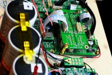
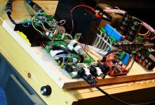
It would be nice if you can post a detilaed picture of your setup.
regards.
Please see the DC power cable,
Attachments
not sure if this is the right place to ask that question, but i will give it a try. Basically i'm considering to run my Buffalo DAC synchronous once the SIC570 clock is available.
What now came into my mind could be an issue with that config is how to be able to use DSD. Plan is is to use Amanero -> Otto -> FIFO -> Buffalo II.
How would the Buffalo get the clock signal when running synchronous in DSD mode ?
What now came into my mind could be an issue with that config is how to be able to use DSD. Plan is is to use Amanero -> Otto -> FIFO -> Buffalo II.
How would the Buffalo get the clock signal when running synchronous in DSD mode ?
Hi Ian
I tested the isolator with power on clock board at 5v.
the input voltage on fifo side is 3.3v which is good.
the voltage on the clock side is 1.7v which is not good.
so I unsoldered all the regulator circuit on the clcok side and the voltage now reads 2.3v on the L pad of the regulator circuit.
everything else is still soldered in place. just the clock regulator circuit is removed. the L pad should read 5v.
any ideas?
regards.
that wont work, fifo runs asynchronously, even with sync clock out, it will be running with no relation to the amanero board timing, how could it be synchronous? also the fifo needs to choose a samplerate and thus clock, based on the input. with no input it wont do anything, bad enough with the dual clock board, even worse with the Si570 which chooses among many different clock speeds
Hi Ian
I tested the isolator with power on clock board at 5v.
the input voltage on fifo side is 3.3v which is good.
the voltage on the clock side is 1.7v which is not good.
so I unsoldered all the regulator circuit on the clcok side and the voltage now reads 2.3v on the L pad of the regulator circuit.
everything else is still soldered in place. just the clock regulator circuit is removed. the L pad should read 5v.
any ideas?
regards.
Could you show me a close picture of your configuration and your clock and isolator board?
Ian
....and now something completely different....
to Ian and all,
I want to share my initial impressions about using the Spidf-Fifo-Clockboard combination. Right out of the box I connected my SBTouch, which was hardly used in the past months because of unfullfilling soudquality, and it was frm the first second a relevation! It sounded like music, which it did never before.
Not connected to my BIII buffalo, but with the nice U-fl connectors and cabels into I2S inputs of Doede new 1794A Dac.
WaneIO connected to the I2S backdoor of the Spdif-board.For playing my canned CD's through XXHighEndPlayer on my PC. This was already a splendid combi but it improved. The crazy thing is, I am talking about the generic clocks that where provided with the set by Ian, just for checking purpose. I look forward to tell you more after implementation of all the proposed refinements to come. Such as better clocks, (I ordered Chrystek957). And waiting for parts to get the Isolator and the managementboard complete... And Lipo4 batt. for the clock?
I will for shure come back on this.
Happy holydays
- Home
- Source & Line
- Digital Line Level
- Asynchronous I2S FIFO project, an ultimate weapon to fight the jitter