AR2, no benefit to syncing titan it wouldnt work anyway as there is a delay for the buffer filling that varies in length depending on sample rate. fifo output is asynchronous wrt the input clock too.
correct, if using the spdif board as well, the only way to get i2s in is via the backdoor mod shown earlier in the thread.
sync mode vs async? a matter of taste really, the jitter is so low from the output of fifo that the pll will not be doing much work anyway. i've been unable to do proper testing to see what I prefer as I havent removed the clock on mt ackodac as yet and I cant run high enough clock speeds on my pre GB 1 fifo board to get fully stable lock in sync mode, stable but every now and then I get a glitch and given i'm running DC coupled amps and digital volume glitches are not so fun. it works leaving the clock unpowered, but i'm thinking the combination of too slow clock speed (22.576 etc) and the fact the onboard unpowered clock is still in parallel, thus messing with the clock edge shape
I would wait a little before buying the clocks, Ian is about to release his Si570 variable mode clock, which will allow 90.3168/98.304MHz. fifo latest version I think will allow 384, perhaps with a little heatsink, Ian can cofirm but thats my understanding. otherwise yes those speeds you mention are correct.
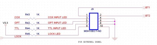
afaik most status LEDs and switching are available on the J9 output header
selecting button is pin 1-2
coax LED is 3 + 4 -
optical LED is 5+ 6-
TTL LED is 7+ 8-
spdif locked LED 9+ 10-
for using external button i'm not sure other than I know it can only cycle through the selections, no direct selection, so you would have to press to cycle just like the onboard, or program multiple presses for one press with arduino etc.
correct, if using the spdif board as well, the only way to get i2s in is via the backdoor mod shown earlier in the thread.
sync mode vs async? a matter of taste really, the jitter is so low from the output of fifo that the pll will not be doing much work anyway. i've been unable to do proper testing to see what I prefer as I havent removed the clock on mt ackodac as yet and I cant run high enough clock speeds on my pre GB 1 fifo board to get fully stable lock in sync mode, stable but every now and then I get a glitch and given i'm running DC coupled amps and digital volume glitches are not so fun. it works leaving the clock unpowered, but i'm thinking the combination of too slow clock speed (22.576 etc) and the fact the onboard unpowered clock is still in parallel, thus messing with the clock edge shape
I would wait a little before buying the clocks, Ian is about to release his Si570 variable mode clock, which will allow 90.3168/98.304MHz. fifo latest version I think will allow 384, perhaps with a little heatsink, Ian can cofirm but thats my understanding. otherwise yes those speeds you mention are correct.
afaik most status LEDs and switching are available on the J9 output header
selecting button is pin 1-2
coax LED is 3 + 4 -
optical LED is 5+ 6-
TTL LED is 7+ 8-
spdif locked LED 9+ 10-
for using external button i'm not sure other than I know it can only cycle through the selections, no direct selection, so you would have to press to cycle just like the onboard, or program multiple presses for one press with arduino etc.
Last edited:
I didn't realize this was being offered fully-assembled. Can I implement this with very basic soldering skills or is it experts-only?
The kit / modules are shipped fully assembled, depending on your specific need, basically no soldering is necessary.
well it would be VERY unlikely that none were needed since the output clock connections are unlikely to match any dac exactly, the closest to a match is the ackodac and even it needs the w.fl rather than u.fl connectors. the units themselves are ready/finished, but the connection to the dac still needs making at the minimum
Ian, before I get my hands busy, a few questions if my understanding is correct. My configuration: Lightharmonic USB to I2S board, ES9012 DAC, FIFO board with S/PDIF board and dual clock.
1. If S/PDIF board is used, does using I2S signal from my USB board, is possible only through additional I2S input port on S/PDIF board?
2. My assumption is that DAC would work the best if used in synchronous mode with FIFO? My USB board also allows to be used as slave ( in master mode uses two clocks with automatic switching) Is it possible to send clock signals to both DAC and USB board? For slave mode I would need to send both clock signals? Or I would be better to leave USB board and just to sync DAC?
3. If I am to use front panel mounted input switching, do I replace your switch with any momentary switch? I need to allow for switching between two sources - S/PDIF and I2S from the board. I will not be sending any S/PDIF signal out.
4. What are the specs for LEDs or your board if I am to replace them with front panel mounted LEDs? I am thinking of taking off LEDs from the board and run wires to the front panel mounted LEDs for input markings.
5. Lastly, I am thinking of buying clocks in the following speeds for the dual clock board - 45.1584 MHz and 49.152 MHz, are these OK for ESS 9012? I am aware that FIFO board doesn't cover 384 KHz, but it goes up to 192KHz.
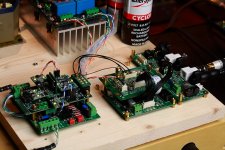
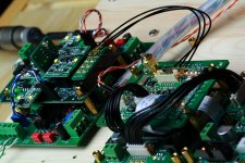
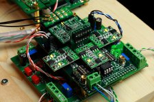
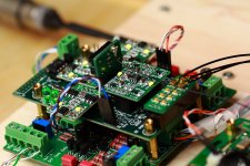
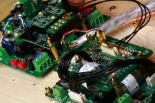
Here are few images of USB board and front panel board that already has switches and LEDs, that I would like to utilize. That board was preexisting and I am able to utilize it withs some modifications. That is explanation for questions No. 4.
Thank you
Vladimir
AR2, no benefit to syncing titan it wouldnt work anyway as there is a delay for the buffer filling that varies in length depending on sample rate. fifo output is asynchronous wrt the input clock too.
correct, if using the spdif board as well, the only way to get i2s in is via the backdoor mod shown earlier in the thread.
sync mode vs async? a matter of taste really, the jitter is so low from the output of fifo that the pll will not be doing much work anyway. i've been unable to do proper testing to see what I prefer as I havent removed the clock on mt ackodac as yet and I cant run high enough clock speeds on my pre GB 1 fifo board to get fully stable lock in sync mode, stable but every now and then I get a glitch and given i'm running DC coupled amps and digital volume glitches are not so fun. it works leaving the clock unpowered, but i'm thinking the combination of too slow clock speed (22.576 etc) and the fact the onboard unpowered clock is still in parallel, thus messing with the clock edge shape
I would wait a little before buying the clocks, Ian is about to release his Si570 variable mode clock, which will allow 90.3168/98.304MHz. fifo latest version I think will allow 384, perhaps with a little heatsink, Ian can cofirm but thats my understanding. otherwise yes those speeds you mention are correct.
afaik most status LEDs and switching are available on the J9 output header
selecting button is pin 1-2
coax LED is 3 + 4 -
optical LED is 5+ 6-
TTL LED is 7+ 8-
spdif locked LED 9+ 10-
for using external button i'm not sure other than I know it can only cycle through the selections, no direct selection, so you would have to press to cycle just like the onboard, or program multiple presses for one press with arduino etc.
Panel interface schematics just for reference.
Ian
Attachments
I didn't realize this was being offered fully-assembled. Can I implement this with very basic soldering skills or is it experts-only?
I couldn't 100% gurantee even if it was soldered by myself with tools and skills not that 'basic'
 .
.To assemble it by yourself, if you have SMT experience, shouldn't be any problem. If no, then you can learn some skills from youtube, it might be OK but need to take some risk
.Ian
Can my Wavelength Proton USB DAC be easily used with the FIFO board or would I be better off with another DAC?qusp said:well it would be VERY unlikely that none were needed since the output clock connections are unlikely to match any dac exactly, the closest to a match is the ackodac and even it needs the w.fl rather than u.fl connectors. the units themselves are ready/finished, but the connection to the dac still needs making at the minimum
If I start over with only a computer, what would be the ideal and easiest setup for the FIFO board?
Does the FIFO board provide galvanic isolation so that EMI can not be conducted from the computer to the DAC?
Does galvanic isolation block EMI?Does the FIFO board provide galvanic isolation so that EMI can not be conducted from the computer to the DAC?
I would think EMI flow right through just like any AC unless some kind of filter is also implemented.
yep, galvanic isolation would block EMI (mostly carried on power supply and ground) unless its radiated EMI, which is usually quite local. however the fifo itself isnt galvanically isolated unless you use the spdif input board, rather than i2s. if you are using 192kHz content or less then I would recommend just using the optical input, others might have irrational beliefs that somehow i2s input will still be superior even with the fifo in place, but i'm not one of them.
What EMI are we refering to? or are you just refering to the general background noise generic to all digital systems (even the FIFO board will create some background noise, all digiatl systems do), and if so what is your concern with this noise (and NO the noise it not just SMPS's, it is created more due to numerous gates switching simultaneous.
i'm not concerned personally, I was just answering the query. i'm presuming hes worried about EMI transmitted on the power supply and ground from the PC
I posed the same q to him here, where you have also noticed the theme
I do however see optical combined with fifo as a pretty good solution to all that, given it cuts down the possible sources of ground contamination of all sorts
I posed the same q to him here, where you have also noticed the theme
I do however see optical combined with fifo as a pretty good solution to all that, given it cuts down the possible sources of ground contamination of all sorts
Last edited:
Does galvanic isolation block EMI?
I would think EMI flow right through just like any AC unless some kind of filter is also implemented.
Since there are USB2 isolators available, I wonder if an isolator (such as the NVE devices) between the FIFO board and the Clock board would be beneficial.
Run ESS9018 at SYNC mode with 98.XXX, 90.XXX MHz MCLK from FIFO and Si570 clock board
Quite a few coding jobs of the MCU FW of the Si570 based clock board were finished. Now I can run my ESS9018 (BIII) at synchronized mode with 98.3040 and 90.3186 MHz MCLK from FIFO and Si570 clock board.
The configuration is almost as same as running sync mode from the dual xo clock board except the MCLK frequencies. It sounds wonderful just as I expected. Now the maximal Fs is confirmed working at up to 390 KHz or bit higher without any problem. MCLK is running at 2048*Fs for both 44.1 KHZ and 48 KHz. Stacking the clock board on top of the FIFO board also tested bit-perfect for 98.xxx MHz MCLK at 384KHz.
Compare with 45.xxx and 49.xxx MHZ, running ESS8018 at SYNC mode by an external MCLK closing to 100 MHz is really a challenge. Here are some comments:
1. MCLK U.FL cable should be as short as possible. Higher quality cable is expected to be better result.
2. The DC input voltage range of the Si570 board is 4-5.5V (6V tested no problem but not recommended). I found with 4V and 5.5V it sounds slightly different. But it’s very hard to tell which one is better. I suspect there is a sweet point of input voltage for ADP151, but I’m not sure what that voltage is.
3. Although the Silabs official document mentioned that Si570 is not quite sensitive to the PSU noise, I found it’s not true, at least for this application. The close-in phase noise performance of Si570 is not as good as CCHD950, 957. So, to compete with them, Si570 need better low noise PSU. Both 1/f noise of PSU and the XO crystal itself contribute to the close-in phase noise. After I bypassed the on board low noise LDO and make the Si570 directly powered by a LiFeP04 3.4V battery cell, ESS9018 sounds better with more details and more liquid.
Si570 is a bit special case. It comes with whole DSPLL circuit but a pure XO. I’ll design a battery manager board later on to make the battery as a standard equipped power supply rather than just a testing configuration.
4. Another discovery is, ESS9081 sounds different for a same 44.1 KHz stream with different MCLK frequencies, for example 45.1584MHz and 90.3168MHz. Hard to tell which one is better, but the sound style is a bit different indeed. I know it’s the internal up-sampling digital filter, different performance for different MCLK.
By taking the advantage of Si570 variable frequency output capability, I designed 4 groups of MCLK and *Fs combination in the Si570 control FW. Group is selectable according to different personal preference, or makes it suitable for different DAC chips. They are:
//Group1:Si570 frequency and *Fs combination for low mclk range
{F112896, 256*FS}, //2 44.1 KHz
{F122880, 256*FS}, //3 48 KHz
{F225792, 256*FS}, //4 88.2 KHz
{F245760, 256*FS}, //5 96 KHz
{F451584, 256*FS}, //6 176.4KHz
{F491520, 256*FS}, //7 192 KHz
{F903168, 256*FS}, //8 352.8KHz
{F983040, 256*FS} //9 384 KHz
// Group2:Si570 frequency and *Fs combination for low mid mclk range
{F225792, 512*FS}, //2 44.1 KHz
{F245760, 512*FS}, //3 48 KHz
{F225792, 256*FS}, //4 88.2 KHz
{F245760, 256*FS}, //5 96 KHz
{F451584, 256*FS}, //6 176.4KHz
{F491520, 256*FS}, //7 192 KHz
{F903168, 256*FS}, //8 352.8KHz
{F983040, 256*FS} //9 384 KHz
// Group3:Si570 frequency and *Fs combination for middle mclk range
{F451584, 1024*FS}, //2 44.1 KHz
{F491520, 1024*FS}, //3 48 KHz
{F451584, 512*FS }, //4 88.2 KHz
{F491520, 512*FS }, //5 96 KHz
{F451584, 256*FS }, //6 176.4KHz
{F491520, 256*FS }, //7 192 KHz
{F903168, 256*FS }, //8 352.8KHz
{F983040, 256*FS } //9 384 KHz
// Group4:Si570 frequency and *Fs combination for high mclk
{F903168, 2048*FS}, //2 44.1 KHz
{F983040, 2048*FS}, //3 48 KHz
{F903168, 1024*FS}, //4 88.2 KHz
{F983040, 1024*FS}, //5 96 KHz
{F903168, 512*FS }, //6 176.4KHz
{F983040, 512*FS }, //7 192 KHz
{F903168, 256*FS }, //8 352.8KHz
{F983040, 256*FS } //9 384 KHz
Group1 is designed for low MCLK frequcncy applications (NOS DACs), group2 is for classical DS DAC while group3,4 are for ESS9018. The selection can be made at any time by holding the on board button, the selected setting will be saved into on board flashing memory as well.
5. More researches to the ESS9018 register settings are needed for getting ‘the last drop of juice’ with SYNC mode and different MCLK frequencies. Different options may suitable for different preference.
Ian
Attachments
Dear Ian,
Thank you very much for your replies to my questions!
MCLK with MHz of nineties is a big present for ES9018 users!
Thank you very much for your replies to my questions!
MCLK with MHz of nineties is a big present for ES9018 users!
Doesn't Crystek supply CCHD-950 of 90.3168MHz or 98.304MHz to non-bulk purchase customer?The close-in phase noise performance of Si570 is not as good as CCHD950, 957.
According to my experience, you need the MCLK higher than 90MHz when you play 352.8 kHz sources without any noise, setting OSF = ON.Another discovery is, ESS9081 sounds different for a same 44.1 KHz stream with different MCLK frequencies, for example 45.1584MHz and 90.3168MHz. Hard to tell which one is better, but the sound style is a bit different indeed. I know it’s the internal up-sampling digital filter, different performance for different MCLK.
Some Japanese users say "jitter reduction = OFF" brings a different result. But, I'm not sure.More researches to the ESS9018 register settings are needed for getting ‘the last drop of juice’ with SYNC mode and different MCLK frequencies.
indeed, very happy here.Dear Ian,
Thank you very much for your replies to my questions!
MCLK with MHz of nineties is a big present for ES9018 users!
no only special order with MOQDoesn't Crystek supply CCHD-950 of 90.3168MHz or 98.304MHz to non-bulk purchase customer?
According to my experience, you need the MCLK higher than 90MHz when you play 352.8 kHz sources without any noise, setting OSF = ON.
Some Japanese users say "jitter reduction = OFF" brings a different result. But, I'm not sure.
yeah I havent been able to decipher any improvement with jitter reduction = off either, probably because the only times i've thought to try it has been with very low jitter sources already in place.
very keen to try this out Ian
I'd love to get in on this FIFO thing. If someone could tell me what to buy (including a DAC) and how to hook them up, I would follow their instructions faithfully.
Ultravox - SGD70.00 : Welcome to the diyparadise e-store!
I powered it with an SLA battery. It seemed to cut out EMI (smoother, no more edgy highs, non-fatiguing) but it also got in the way somehow and degraded the sound in another way. I would call it presence and dynamics. I didn't notice until I upgraded my amp.
Please correct me if I'm wrong, but I think an SPDIF connection *can* be optical and you're saying I should use an optical SPDIF connection with the FIFO in order to achieve galvanic isolation?qusp said:the fifo itself isnt galvanically isolated unless you use the spdif input board, rather than i2s. if you are using 192kHz content or less then I would recommend just using the optical input
I've used this which is based on the ADUM4160:glt said:Since there are USB2 isolators available, I wonder if an isolator (such as the NVE devices) between the FIFO board and the Clock board would be beneficial.
Ultravox - SGD70.00 : Welcome to the diyparadise e-store!
I powered it with an SLA battery. It seemed to cut out EMI (smoother, no more edgy highs, non-fatiguing) but it also got in the way somehow and degraded the sound in another way. I would call it presence and dynamics. I didn't notice until I upgraded my amp.
correct, optical gets a bad rap for direct spdif connection because it has higher jitter than perfectly implemented electrical spdif, due to its need to convert from electric to light and light to electric; but here with the fifo the 2 have the same end result. if you dont need higher than 192kHz (the normal limit for optical transmitters/receivers) then just use optical, by its optical nature there is no electrical connection, so yes of course its galvanically isolated. there are ways to isolate i2s/usb, but they are not without their own issues. Optical is a simple way to completely isolate the connection
correct, optical gets a bad rap for direct spdif connection because it has higher jitter than perfectly implemented electrical spdif, due to its need to convert from electric to light and light to electric; but here with the fifo the 2 have the same end result. if you dont need higher than 192kHz (the normal limit for optical transmitters/receivers) then just use optical, by its optical nature there is no electrical connection, so yes of course its galvanically isolated. there are ways to isolate i2s/usb, but they are not without their own issues. Optical is a simple way to completely isolate the connection
Optical is obviously getting a bad rap due to poor receiver implementations and marketing.
As a matter a fact - non of the interfaces should make a difference - and we as users shouldn't bother about what interface to choose - as long as data integrity is kept and the receiver is able to recover the stream properly.
This project "might" confirm above the way to go. Though I'm still not really convinced about it. I'm wondering if "Ultimate Weapon" implies "The Final Word".
Many manufacturers claim this, but fail on proving it. Many examples show that a little noise, a little timing variations , a different USB/SPDIF/Toslink cable - on the line can cause "severe" ( in audiophile terms ) sound degration (talking about a 6k DAC). (just had a discussion about it over at AA)
And then: Talking about "The final word".
Ian still seems to be on the learning curve. We - the Golden Ear community - are firing our Sabres with several LiPoFe4 since years. And Ian just confirmed what difference it makes on his product using those batteries.
I can tell from my experience, it's getting better with 2-3-4 LiPos in parallel.There are others saying that the right regulator would outperfrom LiPoFe4 again.I'm pretty optimistic that we'll have something to talk about for the next coming years.
For now I'll keep lurking around. Good luck. Enjoy.
well i'm convinced, being that i've been using it for some time now and given each unit goes through data integrity testing before going out. its more than theory for me, not only does the theory say there should be no difference between them, it certainly has been confirmed subjectively in my testing. the only reason i'm still using USB is for multichannel
...its more than theory for me, not only does the theory say there should be no difference between them...
If you say so...
...never heard about that "theory" though.
- Home
- Source & Line
- Digital Line Level
- Asynchronous I2S FIFO project, an ultimate weapon to fight the jitter