For a price you can get one part. (They will throw the other 1000 in a box most likely. . .) Usually making one or a very few is difficult since not every part makes it from start to finish. 22, 24, 45 &49 are standard parts. For digital audio the lower frequencies can easily be a divide option. Higher frequencies become a different oscillator design. If you look at the plots on the Crystek datasheets for the CCHD 957 and the CCHD950 you will see that the close in phase noise is higher for the high frequency oscillators. Its driven by physics (and the q possible in the resonator). For the 90+ MHz needed for the ESS chips I would use a good doubler circuit (lowest phase noise) from the 45+ MHz oscillators. The additional parts are cheap. A minicircuits xfmr, two diodes and a fast (74AC) gate most likely would do it.
haha thanks mate, food for thought I had thought about using Jims supergain block from AN67f (LT) but would still be in the same or similar position for covering all F/S without some way to MUX the premultiplier/post-multiplier output
hey Ian: repurposed levelshifting board + chhd957?
hey Ian: repurposed levelshifting board + chhd957?
Last edited:
For a price you can get one part. (They will throw the other 1000 in a box most likely. . .) Usually making one or a very few is difficult since not every part makes it from start to finish. 22, 24, 45 &49 are standard parts. For digital audio the lower frequencies can easily be a divide option. Higher frequencies become a different oscillator design. If you look at the plots on the Crystek datasheets for the CCHD 957 and the CCHD950 you will see that the close in phase noise is higher for the high frequency oscillators. Its driven by physics (and the q possible in the resonator). For the 90+ MHz needed for the ESS chips I would use a good doubler circuit (lowest phase noise) from the 45+ MHz oscillators. The additional parts are cheap. A minicircuits xfmr, two diodes and a fast (74AC) gate most likely would do it.
That's a good idea. But the low phase noise doubler would be the key part
") . Any reference design?
. Any reference design?Ian
Ian, could the board or firmware be rejigged to allow the dual clock board to contain say a 45.1584 plus 98.304 XO's? then the only speeds not covered would be 48kHz and 354.x kHz which in my world are pretty rare
DAT's and DVD's aren't rare.
Ian, is there any news on the PCM conversion board? I counted 3 threads in the last three days on this forum with people asking for a solution not know that your fifo with a pcm converter would be perfect for. With all the focus on the ESS9018 most multibit folks aren't following this thread.
Hi Regal,
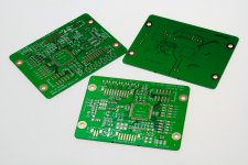
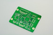
Got the I2S to PCB convertor daughter board PCBs.
I'm thinking about your suggestion opening a new thread for this project. Because this project is becoming a universal I2S to PCM convertor, it could not only interface with FIFO KIT but also interface with any I2S sources together with MCLK. All NOS DAC will benefit from this projcet, even TDA1541
. The FPGA/CPLD design is 100% synchronized logic and the output timing will exactlly fit those NOS DACs.Regards,
Ian
Attachments
DAT's and DVD's aren't rare.
A.D.D? you choose to see only what you can argue with and then somehow reply without actually taking it in... quite a feat.
you disagree that I have little need for my audio rig to play 48kHz and 352kHz? you know what? I care not, it matters not …
Ian, could the board or firmware be rejigged to allow the dual clock board to contain say a 45.1584 plus 98.304 XO's? then the only speeds not covered would be 48kHz and 354.x kHz which in my world are pretty rare
I dont and never will watch DVDs (more likely to be 96kHz these days anyway) on my dac with fifo, I have another dac to use for that via optical spdif, the variable frame delay causes sync issues. This is solvable by delaying the video the same amount, but i'd much rather have a dedicated music system. I watch quite a bit of online movies and TV, which have unpredictable delays that are impossible to account for.
and sorry but DAT not rare? are you kidding me? not rare? haha...
hands up any members using DAT tape with fifo (not you Ian)
Hi Ian
thanks for the good project.
.
I have few Q
.
1. Are the USB interface board working on Mac OSX. If so give please more info about that?
2. Is there a possibility to have instead I2S which is normaly L/R latched
option for L/L and R/R, or for that purpose 2 pieces of fifo is needed?
3. Is there some posibility to have beside I2S, other digital input formats such as the BB and AD used in their dac chips?
.
thanks
ciao
Hi Ian
thanks for the good project.
.
I have few Q
.
1. Are the USB interface board working on Mac OSX. If so give please more info about that?
2. Is there a possibility to have instead I2S which is normaly L/R latched
option for L/L and R/R, or for that purpose 2 pieces of fifo is needed?
3. Is there some posibility to have beside I2S, other digital input formats such as the BB and AD used in their dac chips?
.
thanks
ciao
Is somewhere some web site to inform about specs...
To avoid reading the very long topic from the beginning
trying to reach the info?
Thanks
Sorry I forgot to ask:
Will the hardware support some possible new software in the future
or it will deserve a new hardware boards?
thanks again
.
regardless of the answers
probably i will order
the device
.
thanks
Hi Zoran,
1, There are a lot of USB based digital audio interface working for Mac and PC, even from members of this website. But I don't supply them, sorry about that
.2, I'm working on a I2S to PCM convertor daughter board right now which is synchronized low jitter design specilized for NOS DACs such as AD1865,62, PCM63,PCM1704 and TDA1541... with LL and LR. You can find some details form the post and below:
http://www.diyaudio.com/forums/digi...imate-weapon-fight-jitter-34.html#post2983230, But I don't know if I have chance to supply it. I's up to how many people want.
3, By using the above daughter board, you can have digital audio format accepted by AD and BB NOS DACs, other than I2S
4, You can go the GB II post to download the techincal documents which is kind of summarize of this long thread.
http://www.diyaudio.com/forums/grou...s-pdif-fifo-kit-group-buy-40.html#post3093337
5, FIFO firmware is upgradable, as well as the clock boards. Except you want a totally different design such as a multi channel or DSD. I upgraded the FW from V3.33 to V3.80 recently without changing any on the hardware.
Thank you for interesting.
Ian
Last edited:
there is no USB interface board
Yes indeed right thanks
i want this to be written
:
"3.S/PDIF Interface Board $89- USD/ea
Including:
- An assembled and tested S/PDIF Interface Board
- Two 5” double-ended PH 2.0mm 7-pin I2S cables
- One 6” double-ended U.FL coaxial cable for MCLK output
- One 2” 10-pin FPC/FFC cable to interface with the I2S FIFO Board
- Two BNC to RCA adapters
".
Maybe I switch from word USD to USB
But I don't know if I have chance to supply it. I's up to how many people want.
Ian You want to say that there is no boards on stock?
And that depend on number of ordered boards if it is even made?
Is it for all boards od just I2S-to-PCM?
thanks
Last edited:
you really should have a read of the threads. afaik there are no fifo boards left from this run, none of them, it sold out a few weeks ago, so you will have to put your name on the waiting list for the next round, the level shifting board will only get ordered if there is sufficient interest. these are high grade multilayer boards, a small run would be VERY expensive
Hi Ian
I am writing the Arduino program to select the input of your S/PDIF and indicate on the LCD, there is no LED for the backdoor I2S on the connector for external control panel interface. Any other way for me to get the signal?
If all of the three LEDs are on at same time, it indicates that the selected source is I2S
. Ian
If all of the three LEDs are on at same time, it indicates that the selected source is I2S
Ian
Ian, thanks for your reply. I did some measurement on the 10 pins and found the following :
Niether Pin 1 nor 2 is connected to GND, and I can't measure any voltage on both pins, should I need a relay to short these pins for input selection?
Pins 3, 5, 7 are GND, and 2, 4, 6 can provide logical high for input detection.
Pin 9 and 10 are not connected to GND or 5V, so I need additional circuit to provide logic "high" for SPDIF lock indication.
Are my measurement and assumption correct?
- Home
- Source & Line
- Digital Line Level
- Asynchronous I2S FIFO project, an ultimate weapon to fight the jitter