If you took a close look at the pictures, you may find out, at the clock section, I have different design idea. My design idea on the clock board is kind of open concept... Comparing with the benefit it brought, that MCU is worth it. To keeping bring the ‘fun’, I’ll design series of clock boards, this is only the first one.
Thanks for the explanation. I now understand. The difference between our approaches is that I chose to implement the switch control functions in the main FPGA, be it PLL or DDS or blunt switching.
On the other hand, my I2S FIFO is working at slave mode; the clock board is the master device with highest priority. All of signals are generated by the clock board at finial stage in order to get the better jitter performance. I don’t think using a slave device to dominate the master frequency control is a good idea. Sorry, at this point, I couldn’t agree with you.
I agree that during normal operation, the FIFO is in slave mode, but when the input sample rate changes, the clock has to change asap to avoid missing input data, otherwise the FIFO will overflow/underflow in no time, or gives out pitch shifted output, fun but not really HiFi.
 If the FIFO chip is also responsible for detecting the sample rate changes, it needs to *dominate* the frequency selection, if you prefer that word.
Talking about the relay, I couldn’t find anything more suitable for this double XO configuration other than it, unless you power and run the two XOs at same time which is the way I don’t like. Comparing with FPGA and other logic switching circuit, to switch between clocks, the relay almost introduces no additive jitter. That was the reason I use it. Yes you are right, some of the relays may not suitable for switching the clock, but not include the one I selected. You may notice the good high frequency performance from the insertion loss plot I attached (below 0.1dB at 20 Mhz, below 0.8dB at 1 GHz). Regarding to the impedance match, of course, the dedicated RF relay comes with better performance. But how much we could gain from it? Just let me figure it out. The RF relay could be considered as a half inch cable which we could hookup the source terminate resistor Rs before, while, the non-RF relay could be considered as a half inch lead which we have to hookup the Rs after. The only difference in between is without or with that half inch of additional lead on the XO output pin. For the MCLK up to 24.5760 Mhz with 1-3ns raising/falling time, I don’t see that half inch will make big difference on the output jitter performance. But anyway, if have chance, I’d like to try the RF relay to confirm this matter.
I'm confused. I assume that you use the relay to switch the clock, thus the claim that the relay almost introduces no additive jitter. But you also say that you don't like running two XOs at the same time. Do you only switch one of the XOs on at any time?
In my work experience, a half-inch wire on a 24.576MHz clock can easily make a "good citizen" electronics product into a piece of crap, in terms of FCC compliance.
About the switching time, thank you for the noticing. I may have some idea to make it shorter. The only thing I have to compromise with is the frequencies detection accuracy which may influence the performance of the synthesizer based clock board I might design later on. Fortunately, Fs changing only happen at the moment when people switching the source but not the moment when it was playing.
Fs could also change on-the-fly, for example, in a Foobar 2000 playlist of mixed sample rate files. You don't want to miss the first couple of seconds of the new song.
Just hope you could re-start your project. I believe different idea may suitable for different platform. Ian
Me, too, and I'm very glad to have the opportunity to discuss with you on these topics. More importantly, I think, we can learn different ideas from each other here.
and the new low jitter clock has 10ps jitter, the reclock flip-flop has 20ps additive jitter
no, only 22.36psand you get 30ps jitter on I2S signals
no, only 22.36ps
and flipflops have only a few ps RMS jitter depending on series (HC,AC,ABT etc) and PSU
Hi Nazar_lv. Thank you so much for the more accurate calculation on the RMS jitter(your are right, should be the root of the square sum), as well as the good news about the flip-flop jitter.
Regarding to this issue, at least three times, I inquired to the FAE from TI, each time, I got the same answer: we don't have any jitter data for those devices, even one time, I talked with them face to face on a techincal meeting. And their suggestion was 'do not use flip-flop generate significant clock signal, use pll'
.I remember the new AUC series flip-flop comes with highest Fmax, and only once, I found its jitter data from a website, if I'm not wrong, it was 9ps, but unfortunately I couldn't find it out again.
Where your data comes from? Could you let me know a bit detail about those data? Have a nice weekend. Ian
Last edited:
Hi Ian, jitter data is from much documents and some friends, some of them were at my site (now hacked)
In attach phase noise plot from McClure Residual phase noise in digital frequency dividers
24MHz/4
as you see for old LS series Phase jitter is only 0.12pS RMS but all this is very dependent from PSU noise (for CMOS devices especially)
Regards,
Nazar
In attach phase noise plot from McClure Residual phase noise in digital frequency dividers
24MHz/4
as you see for old LS series Phase jitter is only 0.12pS RMS
but all this is very dependent from PSU noise (for CMOS devices especially)Regards,
Nazar
Attachments
Fs could also change on-the-fly, for example, in a Foobar 2000 playlist of mixed sample rate files. You don't want to miss the first couple of seconds of the new song.
Good point. I'v got some idea to speed up the switching state machine. Many thanks
.Hi Ian, jitter data is from much documents and some friends, some of them were at my site (now hacked)
In attach phase noise plot from McClure Residual phase noise in digital frequency dividers
24MHz/4
as you see for old LS series Phase jitter is only 0.12pS RMS
Nazar
Then there are practical hardware limitations that spoil the fun. Even DAC chips need logic building blocks like gates and flip-flops.
Simple D flip-flops used for on-chip latching, (synchronous) reclocking or (synchronous) dividers add extra jitter. Here are some examples that illustrate the problem:
CD4013 (CMOS), 325ps
74HCT74, 75ps
74LS74, 65ps
74F74, 26ps
NC7SZ175P6, 13ps
SN74AUC1G80, 9ps
NC7SV74K8X, 5ps
MC100EP52DTG, 1.6ps
1.6ps is about as low as it gets using (P)ECL. But most DAC chips are based CMOS logic, resulting in estimated jitter levels between approx. 5ps and 75ps.
Hi Nazar, I found out that flip-flop jitter data from this website finally. But it seems the result is quite different from what you provided. Which one is more close to the real case?
Here is a potential alternative for fast low noise SSI logic Potato Semiconductor / The GHz TTL/ CMOS IO Interface Logic/ Potato IC The stuff really works and meets the specs, probably better than the specs. And the parts are available from eBay!?? Its unusual to see a semi startup that is so low profile.
Be careful about the common jitter numbers you see published, even by very responsible manufacturers. They are probably correct but usually meaningless for audio. The normal spec is jitter in a 12 KHz to 20 MHz band. This is nice but mostly not going to affect an audio band DAC (or ADC for that matter). The AES has a spec that I think is too conservative, using 100 Hz to 40 KHz as far as I can remember.
Background- the usual jitter spec is for SONET applications for high speed data communications. This has very little to do with audio. The jitter above the sample frequency has no where to go so it can really be ignored. If its mixed with a signal (audio) the IM products are above the reconstruction filter. What happens in an oversampled DAC is a bit harder to imagine but its still probably not an issue. However the low frequency is where the jitter lies anyway. The jitter is derived from the phase noise plot. There are a number of calculators on the web that make this pretty easy. Converts an oscillator phase noise curve to jitter information Looking at the phase noise plots you will see that they all rise a lot at low frequencies. There is some literature that discounts the audibility of low frequency jitter (that why AES stopped at 100 Hz) but I don't really buy that.
The low frequency increase is the nature of a crystal oscillator (or any oscillator) but it can be made much worse with power supply noise. Measuring this is not real easy. Measuring at the state of the art is really difficult. I would be very cautious about spending real money (more than $20) on an oscillator without real verifiable phase noise plots, and especially with a single jitter number.
I would look at jitter in a 10 Hz to 200 KHz band. Below 10 Hz is problematic to get good measurements on and hard to say if it matters. Above 200 KHz will be above the highest common sample rate (192 KHz) Obviously frequency accuracy of any decent oscillator will be way below audibility. I am at a loss on the fascination with rubidium oscillators for audio. They are expensive, take a long time to warm up and don't run at audio frequencies. The ones that "do" use either a DDC or a PLL to steer a crystal oscillator. This is all a good solution for the wrong problem.
Another not well understood issue is the affect the load can have on a crystal oscillator. For measurements they usually use a distribution amp with a very high reverse isolation (150 dB) to prevent the oscillator under test interacting with the reference. This would also be very important for a good audio clock.
And the start up time and retrace of a crystal should be understood. A good oscillator actually takes a while to stabilize. usually the specs are not guaranteed until the oscillator has run for a period, like 24 hours. Some really take weeks or months before they have really settled. Switching oscillators on and off between tracks may really compromise their performance.
Here is a calculator that will put some perspective on this Jitter Calculator Also keep in mind that even the best DAC chips we work with are not good much beyond 22 bits. The rest is really little more than noise.
I have been working on ways to measure jitter (more accessible than a commercial phase noise test set) and power supply noise at very low levels. Both are real engineering problems and will limit progress on low jitter oscillator development if not overcome. Once I know they really work I'll publish the how to but I don't want to waste anyone else's time with dead-ends. I have wasted a lot of my own with those.
Even the ones that don't output at digital audio clock frequencies use both FLL and DDS inside. But the VCXO inside is usually well built and the DDS has low residual phase noise. Overall speaking, it may not be as bad as the off-the-shelf oscillators. At least the manufacturer gives you a typical phase noise plot, which is usually not available for the off-the-shelf oscillators.I am at a loss on the fascination with rubidium oscillators for audio. They are expensive, take a long time to warm up and don't run at audio frequencies. The ones that "do" use either a DDC or a PLL to steer a crystal oscillator. This is all a good solution for the wrong problem.
Once you get deep into this stuff dds (what I meant to say earlier) isn't perfect and can have some unfortunate spurs. The PLL's are pretty good and necessary for a rubidium since the actual frequency of the rubidium is 6.834,682,612 GHz, which doesn't divide down to anything. They do have good oscillators and the dds will provide up to 20 MHz in the FE-5680A but they are not as good as the crystal oscillator would be. However the crystal oscillators are pretty much always 10 MHz ovenized oscillators in the precision stuff.
A generic oscillator (the $3.00 type) will have pretty minimal specs: http://www.vectron.com/products/vcxo/DatasheetVVA.pdf Where the more expensive (way more) will have a more complete spec http://www.vectron.com/products/vcxo/VX-501-Dual.pdf mostly proving you get what you pay for. Notice the complete phase noise and jitter spec in the more expensive oscillator, including the frequency range for the jitter spec.
A generic oscillator (the $3.00 type) will have pretty minimal specs: http://www.vectron.com/products/vcxo/DatasheetVVA.pdf Where the more expensive (way more) will have a more complete spec http://www.vectron.com/products/vcxo/VX-501-Dual.pdf mostly proving you get what you pay for. Notice the complete phase noise and jitter spec in the more expensive oscillator, including the frequency range for the jitter spec.
Hi Ian,the data you posted is irrelevant (stupid) because not specified what type of jitter was measured (random, phase, cycle-to-cycle, RMS or p-p etc) and what equipment and PSU was used.Hi Nazar, I found out that flip-flop jitter data from this website finally. But it seems the result is quite different from what you provided. Which one is more close to the real case?
no, for DS DACs without digital filtering exactly to modulator frequency (it is all DS DACs except CXD2552\2562 and WM8741) it is a problem.The jitter above the sample frequency has no where to go so it can really be ignored.
phase jitter yesThe jitter is derived from the phase noise plot
I would say 10Hz - 10kHzI would look at jitter in a 10 Hz to 200 KHz band
It is only for Nyquist dac, not for DSHere is a calculator that will put some perspective on this Jitter Calculator
Perhaps you can explain it more? Delta Sigma DAC's are supposed to be less sensitive to jitter. Since the sample rate is unchanged but the conversion happens at a much higher frequency I'm not clear what the effect of jitter on the clock system will be. Do the modulations on the clock fold over from the actual clock or the sample rate? Or is there a different mechanism at play?no, for DS DACs without digital filtering exactly to modulator frequency (it is all DS DACs except CXD2552\2562 and WM8741) it is a problem.
Phase jitter, time domain jitter, phase noise, residual FM are all different descriptions of the same phenomena. Some of the conversions are involved but the same stuff underneath.phase jitter yes
Interesting, the HF component may be less important. But its contribution to the jitter number is significant. And jitter has a more significant impact on higher audio frequencies.I would say 10Hz - 10kHz
Here are some numbers for oscillators showing the effect of frequency distribution of noise on jitter.:
Jitter pS for a very high quality oscillator:
10 Hz to 10 KHz = 44 fS,
10 Hz to 100 KHz = 48 fS
10 Hz to 1 MHz = 69 fS
10 Hz to 20 MHz = 234 fS
Finally 10 KHz to 20 MHz (the usual quoted spec) = 41 fS
Most oscillators are not anywhere near this good. The Tent labs published performance translates as follows (and the Tent labs is one of the best available to the DIYer) :
10 Hz to 10 KHz = 365 fS,
10 Hz to 100 KHz = 367 fS
10 Hz to 1 MHz = 377 fS
10 Hz to 20 MHz = 370fS
10 KHz to 20 MHz (the usual quoted spec) = 140 fS
It is only for Nyquist dac, not for DS
Perhaps not, but how would they differ? The underlying issues are the same, intermodulation of the jitter (or phase noise) with the audio output.
You made a really good point about the type of jitter and its measurement. Pk to pk could be much more important and measuring that would be much harder. not to mention cycle to cycle etc.
Even the most realistic measurement of jitter, measuring the effect on the output is usually an averaging process, which may be hiding a lot of sins.
Here is a potential alternative for fast low noise SSI logic Potato Semiconductor / The GHz TTL/ CMOS IO Interface Logic/ Potato IC The stuff really works and meets the specs, probably better than the specs. And the parts are available from eBay!?? Its unusual to see a semi startup that is so low profile.
Hi 1audio, Very good recommendation. I didn't notice those GHz CMOS flip-flop before. Thank you so much
. I like the PECL flip-flop for low jitter application, but the disadvantage is obviously for digital audio projects. The strong point of the GHz logic is the LVTTL/COMO level. There is no any barrier to interface with DACs.
I found their eBay store and bought some 74POG74A already for evaluation. Yes,it's such a low profile company with everything $3- (like a dollar store)
. Hopefully I could get them by the end of next week. IanPerhaps you can explain it more? Delta Sigma DAC's are supposed to be less sensitive to jitter.
I seem to recall that the jitter sensitivity is a function of how the conversion's done. The original breed of DS DACs (Bitstream from Philips - example TDA1547) had switched-capacitor (SC) architecture. This means the clock can jitter but that doesn't translate into an amplitude variation at the DAC's output. The same amount of charge is dumped. I wonder if that's what Nazar was referring to in mentioning 'digital filter' - the Cirrus DACs I think have SC filtering after the DAC itself. I'm not sure if everyone goes the SC route nowadays though, a paper by Bob Adams (ADI) seemed to suggest that AD parts don't, but don't quote me on that
Once you get deep into this stuff dds (what I meant to say earlier) isn't perfect and can have some unfortunate spurs. The PLL's are pretty good and necessary for a rubidium since the actual frequency of the rubidium is 6.834,682,612 GHz, which doesn't divide down to anything. They do have good oscillators and the dds will provide up to 20 MHz in the FE-5680A but they are not as good as the crystal oscillator would be. However the crystal oscillators are pretty much always 10 MHz ovenized oscillators in the precision stuff.
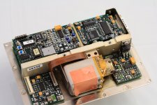
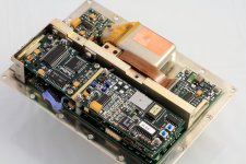
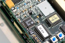
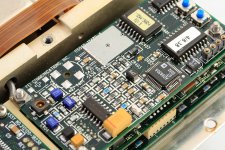
Just attach some pictures of my FE-5680A for you to reference. The frequency was re-programmed to 11.289600MHz. We can see the ADI DDS solution inside. The AD9830 has a 10bit with roughly 50Mhz MCLK and a sine look-up table. It generate the sine clock just as the similar way as a DAC in CD player does. Did anybody see the real output waveform of the AD9830 generating a frequency just around 1/4 Fs? The LPF became a quite significant thing in this case.
I did try this rubidium clock on my CD transport but the result was not as good as I thought. Sine to square converter was another issue. Of course it has perfect frequency stability, but it dosn't mean the low jitter perfermance. It seems the actual performance was not as good as the phase noise plot from the FE-5680 PDF file. I don't know why.
Attachments
Last edited:
Did anybody see the real output waveform of the AD9830 generating a frequency just around 1/4 Fs?
Let's guess - it looks like a NOS DAC reproducing an 11kHz sinewave?
I just bought some AD9850 evaluation boards to have a play with, I'm going to try them with a 50MHz clock and see what I get...
I suspect the problem is the spurs in the phase noise plot for the DDS. The time nuts discuss this and there are issues enough to make them less interesting to the software defined radio guys. Newer DDS's are better but the math may make it quite hard to solve. A PLL can work fine but it would have a very slow lock time if its good. My GPSDO takes a day to lock and continues to get better for as much as a month. Most audiophiles are not that patient unless its a tube breaking in.
You might set up a PLL to phase lock with a long time constant a VXCO to the FE-5680A. But it would make little difference over the VXCO free running. Also the FE-5680A may have some significant EMI. Here is some lifted discussion on DDS with a snaky sounding element that would sell a lot of high end stuff but probably just serve to make things more complex than they need to be (from the Time Nuts mail list):
(I think I need to add that to one of the premium digital file players I'm working on, but I need to figure out what it is first)
You might set up a PLL to phase lock with a long time constant a VXCO to the FE-5680A. But it would make little difference over the VXCO free running. Also the FE-5680A may have some significant EMI. Here is some lifted discussion on DDS with a snaky sounding element that would sell a lot of high end stuff but probably just serve to make things more complex than they need to be (from the Time Nuts mail list):
From bruce.griffiths at xtra.co.nz Sat May 1 21:44:44 2010
From: bruce.griffiths at xtra.co.nz (Bruce Griffiths)
Date: Sun, 02 May 2010 09:44:44 +1200
Subject: [time-nuts] oscillator choice question
In-Reply-To: <650829.58766.qm@web27107.mail.ukl.yahoo.com>
References: <650829.58766.qm@web27107.mail.ukl.yahoo.com>
Message-ID: <4BDCA0CC.6020409@xtra.co.nz>
If there is no electronic tuning available one can use a DDS based
synthesiser to produce a corrected output frequency.
However close in spurs will be problematic unless one use a couple of
simple mix and divide stages or resorts to a Diophantine synthesiser
using phase noise truncation spur free output frequencies from the DDS
chip(s).
Alternatively if one implements the DDS in an FPGA its possible to
virtually eliminate such spurs using a modified algorithm.
However this requires an external DAC to produce the required output.
Bruce
(I think I need to add that to one of the premium digital file players I'm working on, but I need to figure out what it is first)
Google turned up this article which is fairly imformative and not too turgid - Diophantine Frequency Synthesizer Design for Timekeeping Systems
- Home
- Source & Line
- Digital Line Level
- Asynchronous I2S FIFO project, an ultimate weapon to fight the jitter