Quite the opposite.
No insecurity and no need to brag.
It had simply already been done, so somebody has already had this idea before.
And let me repeat, it was pretty obvious.
Instead if you have the RF skills you claim you should notice another possible crosstalk issue.
But obviously you haven't noticed.
No insecurity and no need to brag.
It had simply already been done, so somebody has already had this idea before.
And let me repeat, it was pretty obvious.
Instead if you have the RF skills you claim you should notice another possible crosstalk issue.
But obviously you haven't noticed.
SeinPi vs TWTMC-STS
Nice work Ian on SeinPi and the 3 PS options.
Seems that you find SeinPi with dedicated PS is bringing out more of the potential sound from DRIXO. That could be very cool.
My curiosity still seeks the answer to the great debate. Would SeinPi produce a cleaner square wave than TWTMC-STS and that alone improve perceived sound quality of a FIFOPi/DRIXO rig. Or does it require dedicated ultra power supply to impact the sound. Makes me wonder if it is SeinPi or the PS or both that impacts sound.
In any case I suspect the improved coupling of SMA to FIFO and the clock selection feature will justify SeinPi for many.
I still have curiosity to know the outcome of the great debate wrt square wave shape and its impact on sound. That question will require someone to replace TWTMC-STS with SeinPi without dedicated PS and report on perceived sound quality.
I agree and would have thought that good manners would suggest that such comments would have been better adressed in a personal message.Such a completely unnecessary post. Added noting but showing your insecurity and need for bragging.
//
I agree and would have thought that good manners would suggest that such comments would have been better adressed in a personal message.
Good practice would be to check thoroughly before posting exceptional claims like "Nobody has had this idea before".
It would be as if I were stating that nobody had ever implemented a cascode emitter coupled oscillator, while such kind of oscillator was invented by M.Driscoll and implemented several times.
Good manners would be to thank those who have already done so
The Well Tempered Master Clock - Building a low phase noise/jitter crystal oscillator
Hello,
A few more months like this and people will start looking for another hobby.
There is a rather big group of people who once they finished some diy project they will actually listen to MUSIC and not have their set not working six months in a year because they feel tempted to do the next upgrade will solder is still cooling down.
My next '' project '' will be reducing the number of crappy dc connectors.
Just got a 500$ plus device with a nice diy dc power supply and once this nice '' almost state of the art energy'' arrives at the 500$ device it comes across a connector that is lower quality than the one inside my rear light on my bicycle.
Of course we are being told ( brainwashed) to believe to really take ful advantage of this 500$ device it will need a power supply which will be 500$ or even more as well. The marketing department will give you a list of all the latest sophisticated features used. A thick aluminium engraved front plate but still a 15 dollarcent connection on the print.
It is a shame.
Greetings, eduard
Looking good Ian. I’m probably down for a SinePi as well.
Love the idea of a LiFePo Mini. Especially for someone new to DIY it will be easier to get good results
Hi Ian,
I am also down for 1 sinePi, looks promising.
You are always right (maybe?)! But its not that - its *how* you say it - its so.... insulting...
Please try to phrase your feedback in a nicer way and the forum I think will be happy.
//
And what would the insult be "Sorry to say but it was pretty obvious"?
Pointing out that RF good practice is fairly obvious is not an insult.
And another good RF practice would probably be avoiding two different frequencies cross the same relay.
"Either you get it or you don't - if this is not immediately obvious to you - consider yourself belonging to the latter".
//
The only thing I understand is that by replying to you, I'm wasting my time.
So, since my reply was technical, please keep the discussion technical and tell me what is wrong in my reply.
Andrea, I dont really know much about you but most of the posts Ive seen either here or in your own clock threads usually end the same way..... basically like this. Ive seen the way you respond to people who query your thought process or ideas and its just plain rude, and now youve come on here out of nowhere doing the same thing. You may have a point re. RF stuff on clocks but the way you go about it doesnt particularly encourage healthy and interesting discussion on the topic. And now youre telling people to keep discussion technical whilst you wade in thread-crapping. Probably best to jog on.
Andrea, I dont really know much about you but most of the posts Ive seen either here or in your own clock threads usually end the same way..... basically like this. Ive seen the way you respond to people who query your thought process or ideas and its just plain rude, and now youve come on here out of nowhere doing the same thing. You may have a point re. RF stuff on clocks but the way you go about it doesnt particularly encourage healthy and interesting discussion on the topic. And now youre telling people to keep discussion technical whilst you wade in thread-crapping. Probably best to jog on.
"It looks like somebody has already had this idea before." is a fact.
"Sorry to say but it was pretty obvious." is a tecnhical comment.
These are not my thought process, these are facts and technical comment, no more than this.
I'm sorry if someone does not like them but they remain facts.
And to add something constructive and help the diy audio community, I also posted a technical suggestion: "And another good RF practice would probably be avoiding two different frequencies cross the same relay."
This obviously was ignored, I wonder why I still keep trying to help.
Last edited:
I agree with Andrea regarding the 2 clock signals in one relay; the interference issue is quite obvious when you think about it (I would not have thought of this myself)
But I like the advantage of Sinepi in making a more solid connection with the clock leads not pulling out the pcb of the dil socket.
And I am also interested in the performance of the better square wave.
So I am very keen on third party listening tests between the two devices. As I said before; I am willing to do some testing!")
But I like the advantage of Sinepi in making a more solid connection with the clock leads not pulling out the pcb of the dil socket.
And I am also interested in the performance of the better square wave.
So I am very keen on third party listening tests between the two devices. As I said before; I am willing to do some testing!
@Supersurfer.. I look forward to your listening impression. You have a highly resolved system and are a 3rd party. Doede would be another interesting test subject.
It remains that strong claims were made. Andrea claimed no improvement possible on his squarer. Ian said he thinks yes and took up the challenge. Did SienPi make a difference in sound when only change is the squarer? Inquiring minds want to know
I predict that maybe SeinPi plus another Ian innovation in PS is a game changer. Maybe SeinPi by itself not so much? Still great to have the option of a game changer. SOTA will be expensive, so no complaints if people to choose to take a pass on SOTA. Still an interesting cliff hanger in DIY digital!
Hello,
This shows one of the diy mc prepre amplifier swarming around in the eighties.
Back then it was a combination of big electrolityc caps, NEC 1 F supercap in combination with old fashioned sealed lead batteries. The circuit would just take a few mA.
BUT most builds back then coming from the group around Jean Hiraga paid great attention to the way the power supply was connected to the circuit.
There is no need for gold plated connectors but if you use big F supercaps because you want the lowest esr possible you cannot combine them with connector quality similar to the cheapest mobile phone charger.
Greetings,Eduard
Attachments
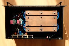
@andrea_mori
Just saw your project. It looks good. Congratulations!
I’ve just noticed that in your design, the two SMA input connectors are sharing the same common ground. That’s fine. In a typical RF design, we usually don’t isolate the signal ground. However, the sine to square converter is a very special circuit. It can be looked upon as a sensitive high gain amplifier bridge between RF circuit and digital circuit. In this case, both ground and power supply noise can easily be modulated into time jitter.
Based on my time jitter measurements, the common mode RF leakage current of the un-selected frequency channel can pollute the SinePi ground if connecting the shield layer of the un-selected coaxial cable directly into the ground, which can increase the RMS time jitter of the finial square clock output by up to 50%, based on the real testing results. To avoid this problem, SinePi uses a special architecture to isolate both RF signals and the ground plate of the un-selected sine clock cable to achieve a much better result.
I understand that you were trying to reduce the crosstalk more by using two relays. However, I saw some possible problems of your sine to square converter as below:
1. There will be no difference between the single relay configuration if you don’t short the un-selected RF signal to the ground. Because the common outputs of the two relays were already connected together.
2. It will be an even worse problem if you short the un-selected frequency channel to the ground by the relay. Because all of that RF energy will be injected directly into the PCB ground layer to result in more crosstalk through ground. No mention of the ground loop. I didn’t see what are the real benefits from your dual relays configuration, unless you change to three relays configuration.
3. It’s not a RF optimized PCB design.
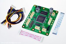
SinePi uses a totally different topology than your design. To reduce the noise and crosstalk, SinePi has only one unified active component for both channels and can make a full signal isolation for any un-selected channels. So I don’t think you can take the credit. But I still want to express my thanks to you for developing several kinds of sine to square converters for the community so that we can get started easier, especially the STS for my FifoPi and McFifo. They are indeed earlier than my SinePi. Please keep in mind that the reason I designed the SinePi was that I want to get the most out of your clocks. I’m your user, I develop SinePi not only for myself and the community, but also for your TWTMC clocks.
I’m sorry for didn’t looking into your project earlier. Your project reminds me of the first generation Fifo I developed ten years ago. I’m the first one who designed a real working Fifo KIT for the audiophiles and made them available for the community. After that time, FIFO has become a very popular product in the audiophile community to improve sound quality. And in the past decade I have been working very hard to carry over this project for generations such as the McFifo series and the FifoPi series. Even Allo didn’t forget to mention that when they released the Kail:
New FIFO buffer for RPI/SBCs
I was hoping I could have your “good manners”.... But...never mind
If you are confident with your sine to square converters, why don’t we start a competition so that the community can gain from the best solutions.
Best regards,
Ian
Just saw your project. It looks good. Congratulations!
I’ve just noticed that in your design, the two SMA input connectors are sharing the same common ground. That’s fine. In a typical RF design, we usually don’t isolate the signal ground. However, the sine to square converter is a very special circuit. It can be looked upon as a sensitive high gain amplifier bridge between RF circuit and digital circuit. In this case, both ground and power supply noise can easily be modulated into time jitter.
Based on my time jitter measurements, the common mode RF leakage current of the un-selected frequency channel can pollute the SinePi ground if connecting the shield layer of the un-selected coaxial cable directly into the ground, which can increase the RMS time jitter of the finial square clock output by up to 50%, based on the real testing results. To avoid this problem, SinePi uses a special architecture to isolate both RF signals and the ground plate of the un-selected sine clock cable to achieve a much better result.
I understand that you were trying to reduce the crosstalk more by using two relays. However, I saw some possible problems of your sine to square converter as below:
1. There will be no difference between the single relay configuration if you don’t short the un-selected RF signal to the ground. Because the common outputs of the two relays were already connected together.
2. It will be an even worse problem if you short the un-selected frequency channel to the ground by the relay. Because all of that RF energy will be injected directly into the PCB ground layer to result in more crosstalk through ground. No mention of the ground loop. I didn’t see what are the real benefits from your dual relays configuration, unless you change to three relays configuration.
3. It’s not a RF optimized PCB design.
SinePi uses a totally different topology than your design. To reduce the noise and crosstalk, SinePi has only one unified active component for both channels and can make a full signal isolation for any un-selected channels. So I don’t think you can take the credit. But I still want to express my thanks to you for developing several kinds of sine to square converters for the community so that we can get started easier, especially the STS for my FifoPi and McFifo. They are indeed earlier than my SinePi. Please keep in mind that the reason I designed the SinePi was that I want to get the most out of your clocks. I’m your user, I develop SinePi not only for myself and the community, but also for your TWTMC clocks.
I’m sorry for didn’t looking into your project earlier. Your project reminds me of the first generation Fifo I developed ten years ago. I’m the first one who designed a real working Fifo KIT for the audiophiles and made them available for the community. After that time, FIFO has become a very popular product in the audiophile community to improve sound quality. And in the past decade I have been working very hard to carry over this project for generations such as the McFifo series and the FifoPi series. Even Allo didn’t forget to mention that when they released the Kail:
New FIFO buffer for RPI/SBCs
I was hoping I could have your “good manners”.... But...never mind
If you are confident with your sine to square converters, why don’t we start a competition so that the community can gain from the best solutions.
Best regards,
Ian
Attachments
Last edited:
Hi Ian,
as I said several times you cannot measure the jitter of the Driscoll oscillator after the sine to square converter unless the resulting jitter was higher than 2 to 7 ps (the noise floor of your digital oscilloscope).
The Driscoll oscillator at 22.5792 MHz has a jitter of 76fs, almost two orders of magnitude lower than the noise floor of your tool, so you have no way to measure it.
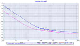
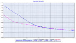
The phase noise of the FIFO buffer output signals has already been measured and published.
The phase noise of the BCK is around -140dBc at 10 Hz from the carrier, better than the phase noise of the sine wave input from the Driscoll oscillator at 24.576 MHz.
The phase noise of the LRCK is around -100dBc at 0.1Hz from the carrier, far better than the phase noise of the sine wave input from the Driscoll oscillator at 24.576 MHz, and the noise floor is the same of the sine wave oscillator.
Evidently the problems you are pointing out do not actually exist by measurements.
Given the results we have achieved with our oscillators (maybe the best oscillators ever built for digital audio) I don't think you can teach us much about RF design and layout, this is just my opinion.
Anyway:
1. the RF signals are properly terminated by using a proper relais configuration following the basic RF rules. We are not the first using such configuration and we would thank those who did it before us.
2. No ground loop and no crosstalk by measurements with both oscilaltors installed, so the real benefits are clear. A phase noise of -100 dBc at 0.1 Hz from the carrier is state of the art result.
3. The phase noise measurements tell that the PCB design is RF optimized.
Just to point out again, we don't want to take any credit, the credits go to those we have thanked several times.
We have never claim we have invented something and we have never said we are the first using such circuits.
We are just very humble and we try to learn from those who are much more skilled than us.
Obviously we choose who to learn from.
Finally, we have designed the STS and the FSDO (with the LTC6957) for the diy audio community and to be used with your FIFOs, so if you'll get better results with your SinePi it will be good for the community.
The only issue is that your measurement will be at least two order of magnitude worse than the sine wave oscillator (at least 2 ps), since you cannot measure a jitter of 76 fs.
The sine to square converter we are designing for our SOTA audio system is totally different, much more complex and expensive.
And also the digital front-end (FIFO) we are designing for our top system is much more complex and expensive, nothing to do with the Lite series.
It will be a 3 chassis device for the FIFO only, we don't design for stacking devices.
Andrea
as I said several times you cannot measure the jitter of the Driscoll oscillator after the sine to square converter unless the resulting jitter was higher than 2 to 7 ps (the noise floor of your digital oscilloscope).
The Driscoll oscillator at 22.5792 MHz has a jitter of 76fs, almost two orders of magnitude lower than the noise floor of your tool, so you have no way to measure it.
The phase noise of the FIFO buffer output signals has already been measured and published.
The phase noise of the BCK is around -140dBc at 10 Hz from the carrier, better than the phase noise of the sine wave input from the Driscoll oscillator at 24.576 MHz.
The phase noise of the LRCK is around -100dBc at 0.1Hz from the carrier, far better than the phase noise of the sine wave input from the Driscoll oscillator at 24.576 MHz, and the noise floor is the same of the sine wave oscillator.
Evidently the problems you are pointing out do not actually exist by measurements.
Given the results we have achieved with our oscillators (maybe the best oscillators ever built for digital audio) I don't think you can teach us much about RF design and layout, this is just my opinion.
Anyway:
1. the RF signals are properly terminated by using a proper relais configuration following the basic RF rules. We are not the first using such configuration and we would thank those who did it before us.
2. No ground loop and no crosstalk by measurements with both oscilaltors installed, so the real benefits are clear. A phase noise of -100 dBc at 0.1 Hz from the carrier is state of the art result.
3. The phase noise measurements tell that the PCB design is RF optimized.
Just to point out again, we don't want to take any credit, the credits go to those we have thanked several times.
We have never claim we have invented something and we have never said we are the first using such circuits.
We are just very humble and we try to learn from those who are much more skilled than us.
Obviously we choose who to learn from.
Finally, we have designed the STS and the FSDO (with the LTC6957) for the diy audio community and to be used with your FIFOs, so if you'll get better results with your SinePi it will be good for the community.
The only issue is that your measurement will be at least two order of magnitude worse than the sine wave oscillator (at least 2 ps), since you cannot measure a jitter of 76 fs.
The sine to square converter we are designing for our SOTA audio system is totally different, much more complex and expensive.
And also the digital front-end (FIFO) we are designing for our top system is much more complex and expensive, nothing to do with the Lite series.
It will be a 3 chassis device for the FIFO only, we don't design for stacking devices.
Andrea
Attachments
- Home
- Source & Line
- Digital Line Level
- Asynchronous I2S FIFO project, an ultimate weapon to fight the jitter