FWIW I thought it was missing some of the SQ present in the earlier version. There is a 10uF cap on the squarer PS. I bypassed it with a HiQ cap and I think the SQ returned only with the better resolution of the improved oscillator. Maybe my imagination.SC-Cut crystals should be very good. As well as the very well designed TWTMC DIRXO.
I highly suspect the sine to square converter board. I'll post some measurement results to confirm.
Ian
Hello,
If bypassing the 10 microfarad cap would be better why wasnt there a bypass installed by Andrea?
Of course almost everyone begins to realize the importance of a good power supply. BUT why just a few people try to improve the connection between the supply the circuit being fed?
If you can reduce cable length with 75% and skip some flimsy connectors?
If the 325F would be really close would the 10 uF still be needed. Maybe then just a tiny film cap could be better?
Greetings,Eduard
"If bypassing the 10 microfarad cap would be better why wasnt there a bypass installed by Andrea?"
Andrea has built his version of the ultimate clock. It is considered SOTA by most who have tried it. But this is DIY so we are entitled to screw it up and imagine its better.
Andrea has built his version of the ultimate clock. It is considered SOTA by most who have tried it. But this is DIY so we are entitled to screw it up and imagine its better.
@A123
But it wasn't the real comparison.
The frequencies are different.
The DACs are different.
I understand, but for someone that miss the boat completely on the Pulsar clocks this is the first impression I have of the rare, elusive Pulsar clock on this thread. So it gives me a general sense of what it can do and what I'm missing.
Once I listen to the TWTC, it will also reinforce whether it's worth the excruciating process of procuring a Pulsar clock if they share similarities.
I'm playing both sides as I hope to have both TWTC (Desktop) and Pulsar (Portable), so I'm more interested in the general qualities of both instead of a direct head to head comparison.
So this is great all around. As @wlowes mentioned, removing the Pulsar and plugging in the STS in it's place may give a fairer comparison.
Adding in a Neutron clock in the mix will be icing, but that seems like a tricky product to get working.
I am trying to get a fifopi Q3 set up for the first time with a Buffalo DAC. I'm trying stock clocks to start, feeding it 3.3v power and external clock but don't get lock on the dac. The green power light comes on but no lock on the DAC and I get no sound. I am using a receiverpi as well with a new Amanero.
Does anyone have any tips?
Does anyone have any tips?
Attachments

@stew1234
Was the Lock LED on FifoPi Q3 lit?
How about the input status LEDs on FifoPi Q3?
RPi free? Did you connect 5V power for FifoPi Pi side? BridgePi doesn't take power from USB (USB power is too noisy).
Ian
Yes, RPi free. I didn't realize I needed to power 5v when not using a RPi. It's working now. Does the 5v on FifoPi also power the reclockerpi module?
Thanks Ian.
@A123
But it wasn't the real comparison.
The frequencies are different.
The DACs are different.
It is strange that you like the crystek more. I cannot listen to the crystek anymore since I build the previous sc-cut driscoll clocks from Andrea. The crystek present a very harsh and rough sound that I cannot stand anymore.
I also built your ess dac with the batteryboard and fifopi and with that configuration the previous driscoll was way ahead of the crystek.
The new drixo clocks are a clear step up in a more clean sound with more insight in the sound stage en more easy to hear small details, the highs are super sweet; detailed but not hard in any way. Try Joni Mitchell Blue album and you can hear that her voice never goes into harshness with the drixo clocks, than try the crystek and you notice what is wrong with them.
PS. The effect of clocks on different dac is very different. I find the effect on a TDA1541A and the dddac with pcm1794 in nos mode more clear than on the ess dac (the ess is also not the best sounding in my setup and to my opinion, I am more fond of the naturalness of nos dacs)
Attachments
Yes, RPi free. I didn't realize I needed to power 5v when not using a RPi. It's working now. Does the 5v on FifoPi also power the reclockerpi module?
Thanks Ian.
No. ReClockPi powered by the 3,3V FifoPi clean side by default. It can also be upgraded to independent 3.3V power supply for even better performance. Ultracapacitor or LifePO4 power supplies are recommended.
Regards,
Ian
DIRXO sounds better too in my system than CCHD957. But still has room to integrate better with FifoPi. I'm working on it now.
https://www.diyaudio.com/forums/dig...mate-weapon-fight-jitter-660.html#post6671042
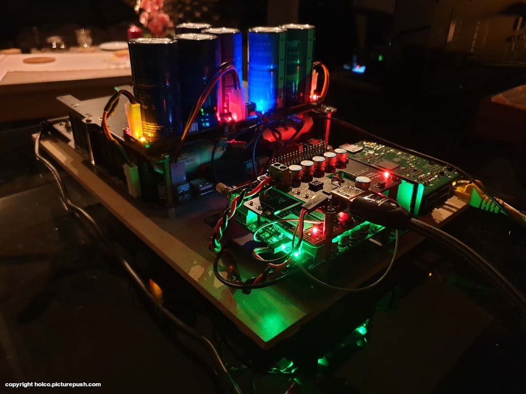
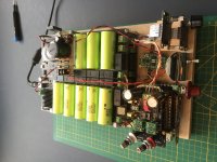
BTW, the best power supply for FifoPi clean side (also for the sine to square convertor) would be the 3000F pure ultracapacitor power supply. It will be tested very soon.
Regards,
Ian
https://www.diyaudio.com/forums/dig...mate-weapon-fight-jitter-660.html#post6671042
BTW, the best power supply for FifoPi clean side (also for the sine to square convertor) would be the 3000F pure ultracapacitor power supply. It will be tested very soon.
Regards,
Ian
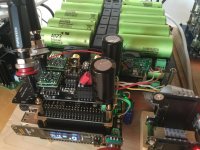
Trying to get the most out of TWTMC clocks for FifoPi system (3)
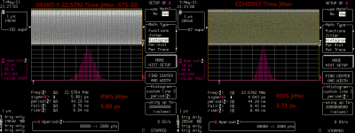
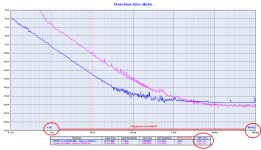
TWTMC-DIRXO-F 22.5792 + TWTMC-STS + 22.5792 SC-cut Time jitter measurement
I did a time domain jitter measurement to TWTMC-DIRXO-F 22.5792 + TWTMC-STS + 22.5792 SC-cut. The result was not as good as I expected.
Testing condition was:
LC584AXL 1GHz Oscilloscope with jitter measurement package
Run at 8 GS/s sampling with 1GHz bandwidth fully opened
50 ohm terminated coaxial cable input
TWTMC-DIRXO power supply: 13.2V LifePO4
TWTMC-STS power supply: pure 3000F ultracapacitor precharged to 3.3V (could be the best PSU in the real world)
The RMS time jitter was measured 5.08ps (with LC584AXL timebase noise floor removed), Which is higher than what it should be.
As a comparison, I did the same test on a CCHD957 22.5792MHz XO. Under exactly the same test condition. CCHD957 RMS time jitter was measured 2.71ps, even better than TWTMC-DIRXO-F 22.5792 followed by TWTMC-STS.
Please see the comparison test results for details. I’m not a qualified/calibrated testing lab, so the testing results could be unfair to Andrea’s products. But the apple to apple comparison testing tells the story. I could be wrong, if anybody is questioning my measurement results, you can duplicate the test by using a high speed digital oscilloscope with bandwidth higher than 1GHz.
So I sent an email to Andrea asking for help. Here are his explanations:
1. Based on the phase noise measurements, Crystek CCHD957 really has better noise floor than the DRIXO followed by the sine to square converter. The jitter I measured in the time domain could be the jitter of the phase noise floor.
2. DRIXO+STS has much better close-in phase noise which can not be measured in time domain by a digital oscilloscope.
3. Jitter noise floor doesn’t affect the sound quality, only close-in phase noise impact the sound quality
While.. what he said... could be...makes sense, because TWTMC-DIRXO-F 22.5792 with TWTMC-STS really sounds better than CCHD957 in my system. However, 2ps more time domain RMS jitter could be too big for such a good clock like the DIRXO. And the total 5ps RMS jitter is just at around 2KHz offset frequency corresponding to the carrier, still within the audible range. Also, for a Sigma-delta DAC, MCLK takes care of the whole process. The THD+N will be degraded if the MCLK jitter noise floor is higher.
I have been looking for really nice clocks for many years. What I’m doing is trying to get the most out of the TWTMC clock, to make it sound the best in my system.
So, I believe there is still something that can be improved. I suspect the STS sine to square converter. I’ll do more tests to confirm.
Other links:
1. https://www.diyaudio.com/forums/dig...mate-weapon-fight-jitter-657.html#post6668751
2. https://www.diyaudio.com/forums/dig...mate-weapon-fight-jitter-660.html#post6671042
Attachments
Hello,
I already saw some tricky mounting of the smaller supercaps. If people are going to use the bigger and heavier 3000F caps in a similar way somewhere somehow something will happen .
So there could be a need for a '' redesign '' of the STS boards. Maybe in certain situations there could be an issue. We better wait for Andrea to react.
Greetings, Eduard
TWTMC-DIRXO-F 22.5792 + TWTMC-STS + 22.5792 SC-cut Time jitter measurement
I did a time domain jitter measurement to TWTMC-DIRXO-F 22.5792 + TWTMC-STS + 22.5792 SC-cut. The result was not as good as I expected.
Testing condition was:
LC584AXL 1GHz Oscilloscope with jitter measurement package
Run at 8 GS/s sampling with 1GHz bandwidth fully opened
50 ohm terminated coaxial cable input
TWTMC-DIRXO power supply: 13.2V LifePO4
TWTMC-STS power supply: pure 3000F ultracapacitor precharged to 3.3V (could be the best PSU in the real world)
The RMS time jitter was measured 5.08ps (with LC584AXL timebase noise floor removed), Which is higher than what it should be.
As a comparison, I did the same test on a CCHD957 22.5792MHz XO. Under exactly the same test condition. CCHD957 RMS time jitter was measured 2.71ps, even better than TWTMC-DIRXO-F 22.5792 followed by TWTMC-STS.
Please see the comparison test results for details. I’m not a qualified/calibrated testing lab, so the testing results could be unfair to Andrea’s products. But the apple to apple comparison testing tells the story. I could be wrong, if anybody is questioning my measurement results, you can duplicate the test by using a high speed digital oscilloscope with bandwidth higher than 1GHz.
So I sent an email to Andrea asking for help. Here are his explanations:
1. Based on the phase noise measurements, Crystek CCHD957 really has better noise floor than the DRIXO followed by the sine to square converter. The jitter I measured in the time domain could be the jitter of the phase noise floor.
2. DRIXO+STS has much better close-in phase noise which can not be measured in time domain by a digital oscilloscope.
3. Jitter noise floor doesn’t affect the sound quality, only close-in phase noise impact the sound quality
While.. what he said... could be...makes sense, because TWTMC-DIRXO-F 22.5792 with TWTMC-STS really sounds better than CCHD957 in my system. However, 2ps more time domain RMS jitter could be too big for such a good clock like the DIRXO. And the total 5ps RMS jitter is just at around 2KHz offset frequency corresponding to the carrier, still within the audible range. Also, for a Sigma-delta DAC, MCLK takes care of the whole process. The THD+N will be degraded if the MCLK jitter noise floor is higher.
I have been looking for really nice clocks for many years. What I’m doing is trying to get the most out of the TWTMC clock, to make it sound the best in my system.
So, I believe there is still something that can be improved. I suspect the STS sine to square converter. I’ll do more tests to confirm.
Thanks Ian for a serious test set-up and sharing. Your extra view in the time domain helps giving an other opportunity to correlate what we hear with what we measure and hence being able to improve on things....
you wrote:
2. DRIXO+STS has much better close-in phase noise which can not be measured in time domain by a digital oscilloscope.
may be stupid question: Is there now way to limit the bandwidth of the jitter noise or deviations from the center frequency? like a A-weighting curve I mean. (not literally of course as you want the low frequencies untouched)
I mean, only taking the variations up to 100Hz or so (close in phase noise) into account and therefor let the higher frequency noise floor not take such a significant part of the integration of the broad bandwidth into the time domain....
I cannot argue about listening impressions since they are subjective, although almost all the members who have listened to the new oscillators have reported the opposite.
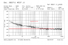
About the measurements, as I have said several times, a digital oscilloscope is not the suitable tool to characterize an oscillator.
Indeed Crystek has used the Agilent E5052 to characterize their CCHD-957 oscillator.
They could have saved several tens of thousands of dollars using a digital oscilloscope rather than the expensive Agilent phase noise analyzer.
But usually a digital oscilloscope has a poor time base, often worse than the DUT, so in the end it measures the noise floor of the oscillator.
There is no doubt that the Crystek CCHD-957 has better noise floor, but we are talking of -170dBc against -157dBc of the Driscoll+STS.
So if you think that the noise floor is the goal and it makes the difference (and keep in mind we are talking of -157dBc) then buy a Crystek and live happy.
But if you think that the quality of an oscillator is the close in phase noise, then the jitter measured with a digital oscilloscope does not explain nothing about the performance of the oscillator.
It's a standalone number without the spectrum of the noise and it depends on the integration bandwidth.
That's the reason why Crystek, NDK and also Wenzel and Oscilloquartz use an expensive phase noise analyzer to measure their oscillators.
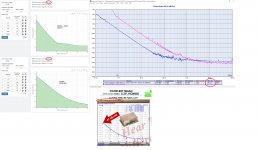
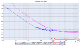
Please, take a look at the following plots to understand how the integration bandwidth affects the phase jitter.
In the first plot the integration bandwidth is 1Hz-100kHz, the RMS jitter is 2.4ps for the Crystek and 160fs for the Driscoll-STS, that's more than one order of magnitude better than the Crystek.
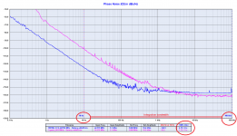
In the second plot the integration bandwidth is 10Hz-100kHz, magically the RMS jitter changes a lot, it's 170fs for the Crystek and 47fs for the Driscoll-STS, still much better than the Crystek but moving the lower limit of the integration bandwidth to higher frequency the difference is less because the noise floor weights more on the calculated phase jitter.
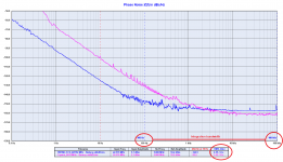
In the third plot the integration bandwidth is 100Hz-100kHz, and magically the RMS jitter changes again, now it's 35fs for the Crystek and 45fs for the Driscoll-STS, the Crystek looks better since the noise floor weights even more.
In the fourth plot the integration bandwidth is 1kHz-100kHz, the standard bandwidth used to measure the jitter for telecommunication applications. The RMS jitter changes again, now it's 27fs for the Crystek and 44fs for the Driscoll-STS, the Crystek looks even better since the noise floor weights even more.
Finally, please take a look at the phase noise plot of the Oscilloquartz BVA 8607, several thousands USD, one of the best oscillator ever built.
The noise floor looks very similar to the Driscoll-+STS, around -157dBc, more than 10dBc worse than the Crystek.
And now ask yourself why is anyone willing to spend several thousand dollars on an oscillator with a noise floor worse than the Crystek CCHD-957 (USD 25).
If you take a look at the phase noise of the BVA oscillator at 1Hz and 10Hz from the carrier against the Crystek you get the answer.
About the measurements, as I have said several times, a digital oscilloscope is not the suitable tool to characterize an oscillator.
Indeed Crystek has used the Agilent E5052 to characterize their CCHD-957 oscillator.
They could have saved several tens of thousands of dollars using a digital oscilloscope rather than the expensive Agilent phase noise analyzer.
But usually a digital oscilloscope has a poor time base, often worse than the DUT, so in the end it measures the noise floor of the oscillator.
There is no doubt that the Crystek CCHD-957 has better noise floor, but we are talking of -170dBc against -157dBc of the Driscoll+STS.
So if you think that the noise floor is the goal and it makes the difference (and keep in mind we are talking of -157dBc) then buy a Crystek and live happy.
But if you think that the quality of an oscillator is the close in phase noise, then the jitter measured with a digital oscilloscope does not explain nothing about the performance of the oscillator.
It's a standalone number without the spectrum of the noise and it depends on the integration bandwidth.
That's the reason why Crystek, NDK and also Wenzel and Oscilloquartz use an expensive phase noise analyzer to measure their oscillators.
Please, take a look at the following plots to understand how the integration bandwidth affects the phase jitter.
In the first plot the integration bandwidth is 1Hz-100kHz, the RMS jitter is 2.4ps for the Crystek and 160fs for the Driscoll-STS, that's more than one order of magnitude better than the Crystek.
In the second plot the integration bandwidth is 10Hz-100kHz, magically the RMS jitter changes a lot, it's 170fs for the Crystek and 47fs for the Driscoll-STS, still much better than the Crystek but moving the lower limit of the integration bandwidth to higher frequency the difference is less because the noise floor weights more on the calculated phase jitter.
In the third plot the integration bandwidth is 100Hz-100kHz, and magically the RMS jitter changes again, now it's 35fs for the Crystek and 45fs for the Driscoll-STS, the Crystek looks better since the noise floor weights even more.
In the fourth plot the integration bandwidth is 1kHz-100kHz, the standard bandwidth used to measure the jitter for telecommunication applications. The RMS jitter changes again, now it's 27fs for the Crystek and 44fs for the Driscoll-STS, the Crystek looks even better since the noise floor weights even more.
Finally, please take a look at the phase noise plot of the Oscilloquartz BVA 8607, several thousands USD, one of the best oscillator ever built.
The noise floor looks very similar to the Driscoll-+STS, around -157dBc, more than 10dBc worse than the Crystek.
And now ask yourself why is anyone willing to spend several thousand dollars on an oscillator with a noise floor worse than the Crystek CCHD-957 (USD 25).
If you take a look at the phase noise of the BVA oscillator at 1Hz and 10Hz from the carrier against the Crystek you get the answer.
Attachments
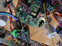
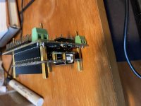
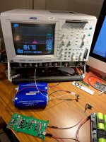
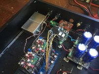
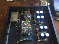
I just received my reclockpi, and all the led’s are glowing, but no sound. I have fifopi Q2 with it’s own 3.3v psu for the clean side. According to the manual it’s recommended to short S1 on reclockpi if fifopi has it’s own 3.3v psu on the clean side. I am using the gpio on the reclockpi to connect the wiring to dddac mainboard. I have tried S1 not shorted, and shorted, but still no sound. Anyone with similar problem ?
Hello,
Especially if you are not that bright about electronics it can be hard to get things working if your '' set up '' is a bit different than usual. Each board having its own manual can be nice but once you have a few boards on your table maybe you just one or two pages ( I have the DDDAC manual laminated) for getting the right assembly would be nice.
Probably for the famous trio it will be clear why it is not working.
The only thing i notice that are a lot of LONG cables.
Greetings, eduard
- Home
- Source & Line
- Digital Line Level
- Asynchronous I2S FIFO project, an ultimate weapon to fight the jitter