I appreciate that. It just so happened my wife was on the phone with the vet as I was typing out that reply, typically I'm not so impulsive.
Fingers crossed we can get her fixed up.
I am also going to order one of those u.fl tools, since to me it seems that removing is where I'm going wrong; putting back together isn't so bad. My hope, though, is that I do not have to disassemble again for awhile - all is working correctly except for a nagging glitch with symphonic-mpd playback.
the tool is good, but a bit pricey. I have found that using a box cutter/stanley knife as a lever underneath, with a finger lightly pressed on top work pretty well. not prying the actual connection off, but rather very close to it where its crimped onto the cable. I also use the blade to apply even downwards pressure when attaching. at one stage I also used a round file to take a small notch out of an old knife, to emulate the official tool, but lost that in my last move.
Thanks for the tips!
I'm at a bit of a crossroads with my project. Basically in a nutshell, I thought I needed one thing (pi-based player + reclocker) when now I'm realizing that I have that already and it really does work fabulously (thought I could improve it). The little ticks and glitches during playback - while infrequent - are still maddening and any inkling of perceived increase in SQ is basically just not worth the potential of expecting those to happen. And I've tried multiple players, two versions of Pi, the stock clocks and AccuSilicon clocks, I'm stumped on that part. But even with those, I just don't think I need the player/Pi portion of my current build vision.
My bias against USB-based digital audio has waned, but with this new setup I have (HQPlayer Pi4 NAA into a USB Denafrips DAC), it sounds... well I don't know what I was thinking that I was going to somehow find some massive improvement.
So I'm thinking I take what I have - battery PSU, FIFOQ3, HDMIPi, and just add a BridgePi and Amanero Combo 384 and at least see to fruition a DDC device that I can run i2S into my DAC, with the DDC being an output from my HQPlayer NAA getting fed Native DSD. Then I can at least compare the two side by side.
Just today I found out my DAC is already using that Amanero 384 input along with supposedly good quality TXCOs.
So if you've made it this far... with the above said, would you expect a LifePO4 battery PSU-powered (yea, way overkill here, I get that) DDC with AccuSilicon AS318 clocks to outperform the conversion that's already taking place in my DAC? Because I'm stuck wondering if I want to spend another $150 with shipping from France to transform the project, or do I just stick with what I've got?
I realize only my ears, my room, my system... but I'm interested in anyone's thoughts. Seems I'm chasing something I probably already have... BUT - I have had a ton of fun getting to where I am, and actually having to use various parts of my brain and hands I haven't had to in awhile. So it's definitely not all for nothing, don't get me wrong.
PS - dog will most likely be fine; got a tummy x-ray and antibiotics. seems like she got into something she shouldn't have, which we have no idea what that could be as everything is covered in snow right now outside, and they can't get into anything inside. Either way, we feel better about that situation now.
Last edited:
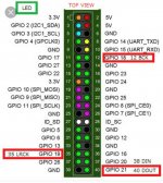
Can someone explain if i need the controller board to use Ian's es9038q2m (first edition) with i2s in from BeagleBone?
Does it depend on synchronous or asynchronous modes?.
I guess the following pins should be enough
BCLK
LRCLK
DATA
GROUND
May be someone have pinout of the dac board.
PS Can not find the right thread to ask, sorry
Does it depend on synchronous or asynchronous modes?.
I guess the following pins should be enough
BCLK
LRCLK
DATA
GROUND
May be someone have pinout of the dac board.
PS Can not find the right thread to ask, sorry
Attachments
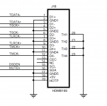
HDMIpi MkII, smoothly switches PCM/DSD, eliminates any possible popping sounds
HDMIpi MkII PCM/DSD/DoP transmitter board was designed to work perfectly with FifoPi Q3 and external DAC by additionally providing both DSDen and MUTE signals over HDMI cable.
The new upgraded features are:
New DSD enable and MUTE signals over HDMI to make it possible to control external DAC switching between PCM and DSD and eliminating any possible popping sound.
Enhanced decoupling capacitor networks to improve power supply performance.
When working with FifoPi Q3, besides MCLK, both DSD and MUTE signals need to be connected to HDMI MkII to make external DAC switching smoothly between PCM/DSD, and to eliminate any possible popping sounds. Please see the pictures for details.
When working with Topping D90, Some settings of Topping D90 DAC needs to be changed from default, otherwise the left/right channel will be reversed. Please hold the power button when you turn on the power switch to enter the setting mode,
1. Change setting 8 to REV
2. Change setting 9 to DSDR/DATA
Previous post:
https://www.diyaudio.com/forums/dig...mate-weapon-fight-jitter-588.html#post6511276

HDMIpiMkIITransmitter by Ian, on Flickr

HDMIpiMkIIFfiPiQ3 by Ian, on Flickr

HDMIpiMkIIFfiPiQ3D90 by Ian, on Flickr
Ian
HDMIpi MkII PCM/DSD/DoP transmitter board was designed to work perfectly with FifoPi Q3 and external DAC by additionally providing both DSDen and MUTE signals over HDMI cable.
The new upgraded features are:
New DSD enable and MUTE signals over HDMI to make it possible to control external DAC switching between PCM and DSD and eliminating any possible popping sound.
Enhanced decoupling capacitor networks to improve power supply performance.
When working with FifoPi Q3, besides MCLK, both DSD and MUTE signals need to be connected to HDMI MkII to make external DAC switching smoothly between PCM/DSD, and to eliminate any possible popping sounds. Please see the pictures for details.
When working with Topping D90, Some settings of Topping D90 DAC needs to be changed from default, otherwise the left/right channel will be reversed. Please hold the power button when you turn on the power switch to enter the setting mode,
1. Change setting 8 to REV
2. Change setting 9 to DSDR/DATA
Previous post:
https://www.diyaudio.com/forums/dig...mate-weapon-fight-jitter-588.html#post6511276
HDMIpiMkIITransmitter by Ian, on Flickr
HDMIpiMkIIFfiPiQ3 by Ian, on Flickr
HDMIpiMkIIFfiPiQ3D90 by Ian, on Flickr
Ian
Attachments
I am using BBB as the endpoint over ethernet for now along with HQplayer. It outputs dsd and mute. I am still experimenting.
I'd like to hook up the es2038q2m board and decide to get fifo and other boards or just leave a minimal configuration for my computer setup.
So BBB (with reclock) to ES9038q2m to transformer output for now
I'd like to hook up the es2038q2m board and decide to get fifo and other boards or just leave a minimal configuration for my computer setup.
So BBB (with reclock) to ES9038q2m to transformer output for now
HDMIpi MkII PCM/DSD/DoP transmitter board was designed to work perfectly with FifoPi Q3 and external DAC by additionally providing both DSDen and MUTE signals over HDMI cable.
The new upgraded features are:
New DSD enable and MUTE signals over HDMI to make it possible to control external DAC switching between PCM and DSD and eliminating any possible popping sound.
Enhanced decoupling capacitor networks to improve power supply performance.
When working with FifoPi Q3, besides MCLK, both DSD and MUTE signals need to be connected to HDMI MkII to make external DAC switching smoothly between PCM/DSD, and to eliminate any possible popping sounds. Please see the pictures for details.
When working with Topping D90, Some settings of Topping D90 DAC needs to be changed from default, otherwise the left/right channel will be reversed. Please hold the power button when you turn on the power switch to enter the setting mode,
1. Change setting 8 to REV
2. Change setting 9 to DSDR/DATA
Previous post:
https://www.diyaudio.com/forums/dig...mate-weapon-fight-jitter-588.html#post6511276
https://flic.kr/p/2kC3UHv
HDMIpiMkIITransmitter by Ian, on Flickr
https://flic.kr/p/2kBZjXn
HDMIpiMkIIFfiPiQ3 by Ian, on Flickr
https://flic.kr/p/2kCWyjX
HDMIpiMkIIFfiPiQ3D90 by Ian, on Flickr
Ian
Dear Ian,
Nice will order HDMIPi MkII, any update on the ReclockerPi? might want to get them together
Thanks
Hi Ian,
Is the HDMI connector at the exact same position as on the TransportPi?
And is the TransportPi getting the same update?
Br,
Mario
Is the HDMI connector at the exact same position as on the TransportPi?
And is the TransportPi getting the same update?
Br,
Mario
HDMIpi MkII PCM/DSD/DoP transmitter board was designed to work perfectly with FifoPi Q3 and external DAC by additionally providing both DSDen and MUTE signals over HDMI cable.
The new upgraded features are:
New DSD enable and MUTE signals over HDMI to make it possible to control external DAC switching between PCM and DSD and eliminating any possible popping sound.
Enhanced decoupling capacitor networks to improve power supply performance.
When working with FifoPi Q3, besides MCLK, both DSD and MUTE signals need to be connected to HDMI MkII to make external DAC switching smoothly between PCM/DSD, and to eliminate any possible popping sounds. Please see the pictures for details.
When working with Topping D90, Some settings of Topping D90 DAC needs to be changed from default, otherwise the left/right channel will be reversed. Please hold the power button when you turn on the power switch to enter the setting mode,
1. Change setting 8 to REV
2. Change setting 9 to DSDR/DATA
Previous post:
https://www.diyaudio.com/forums/dig...mate-weapon-fight-jitter-588.html#post6511276
https://flic.kr/p/2kC3UHv
HDMIpiMkIITransmitter by Ian, on Flickr
https://flic.kr/p/2kBZjXn
HDMIpiMkIIFfiPiQ3 by Ian, on Flickr
https://flic.kr/p/2kCWyjX
HDMIpiMkIIFfiPiQ3D90 by Ian, on Flickr
Ian
Dear Ian,
Nice will order HDMIPi MkII, any update on the ReclockerPi? might want to get them together
Thanks
ReclockPi is under evaluation now. Very promising so far. I'll make it available as soon as possible.
Ian
Hi Ian,
Is the HDMI connector at the exact same position as on the TransportPi?
And is the TransportPi getting the same update?
Br,
Mario
Yes, HDMPi MkII didn't change the position of connectors. You can upgrade directly.
Ian
ReclockPi is under evaluation now. Very promising so far. I'll make it available as soon as possible.
Ian
Dear Ian,
Good to hear that, looking forward for the launch
Best
Video of My Best Sound Quality Audiophile DIY DAC I Built in 2020
The Best Sound Quality Audiophile DIY DAC I Built in 2020 - YouTube
Ian
The Best Sound Quality Audiophile DIY DAC I Built in 2020 - YouTube
Ian
Last edited:
Video of My Best Sound Quality Audiophile DIY DAC I Built in 2020
The Best Sound Quality Audiophile DIY DAC I Built in 2020 - YouTube
Ian
Dear Ian,
Wow nice Video, saw the Reclock Pi & Pulsar OCXO really nice.
Take your time to perfecting it

Does this also mean that you could be able to provide OCXO also as optional

Thank you for your passion and kit
Best
Video of My Best Sound Quality Audiophile DIY DAC I Built in 2020
The Best Sound Quality Audiophile DIY DAC I Built in 2020 - YouTube
Ian
Hi Ian,
great news!!! thank you for the video.
judging by the video, this Reclock Pi has a slightly different composition than I previously imagined.
1. as I understand it, the pulsar clocks are on the fifopi. and it turns out that on the Reclock Pi itself there are no clocks at all. am I right?
2. the Reclock Pi is powered by default from fifopi. but on the board, you can see that it is possible to separate the power supply and supply it separately by 3.3v. am I right?
3. Ian, please tell us what is the fundamental difference from fifopi, which makes the Reclock Pi even more effective than fifopi?
thank you
Video of My Best Sound Quality Audiophile DIY DAC I Built in 2020
The Best Sound Quality Audiophile DIY DAC I Built in 2020 - YouTube
Ian
Wow, that looks amazing!!! And to see you saying it sounds as good any any of your other DACs whilst running it on B&W 802 D3 speakers kind of speaks for itself. Love how the PSU takes up more room than the pi and DAC
Like the previous poster, I was wondering what the reclocker is meant to do that the FIFOpi doesnt already do?
Also, are there any plans for a 12v UCconditioner??
Ian, that looks very impressive!
I'm interested in the fact you are using a uC Conditioner rather than the hybrid to supplement the clock power: is this a path that would provide a slightly better but more cumbersome supply for most situations, or is it only a marginal improvement over the hybrid board that really only provides benefit in critical applications?
Regards, Simon.
Optimal Power to StationPi && BridgePi?
Hey guys,
After frying a few more BMS boards and noticing it's probably going to be too bulky for practical use, I gave up on the Portable/Transportable Project
Portable/Transportable
It didn't work out, but it was a great learning experience and helps me determine my next possible solutions. One lesson learned is it is best to probably go with pins instead of soldering direct to PCB on the BMS, so will incorporate that in the next project. So since I have accumulated extra SuperCaps and UC Condtioners during the GB, I want to make use of those in my SuperCaps Transportable Project. This will be housed in a medium size Pelican case along with a battery-powered DAC. This should be much more straightforward as I will not have to work in tight spaces.
Opinions on the optimal Ian Canada Battery + SuperCaps power solution for StationPi && BridgePi?
SuperCaps Transportable Project
For the StationPi:
For the BridgePi:
I'm having a hard time though with BridgePi as I have just started considering as this is a more stationary Desktop solution. Can I get away with all 3.3V SuperCap?
Do I need 5V SuperCap => Q3 GPIO-side? 3.3V SuperCap => Q3 GPIO-side okay since RPi not in the chain?
I'm not a big USB fan, but I can't justify two StationPi builds. Plus the USB from the PC is data-only and re-clocked + no USB power so I'm good with that, so thinking powering the BridgePi maybe the way to go to optimise..?
Ignore how to power the ReclockPi for now as I just treat that like the ShieldPi and TransportPi (Optional).
Thxs.
Hey guys,
After frying a few more BMS boards and noticing it's probably going to be too bulky for practical use, I gave up on the Portable/Transportable Project
It didn't work out, but it was a great learning experience and helps me determine my next possible solutions. One lesson learned is it is best to probably go with pins instead of soldering direct to PCB on the BMS, so will incorporate that in the next project. So since I have accumulated extra SuperCaps and UC Condtioners during the GB, I want to make use of those in my SuperCaps Transportable Project. This will be housed in a medium size Pelican case along with a battery-powered DAC. This should be much more straightforward as I will not have to work in tight spaces.
Opinions on the optimal Ian Canada Battery + SuperCaps power solution for StationPi && BridgePi?
SuperCaps Transportable Project
- A123 Battery with Tab (2)
- BMS (2)
- UC Conditioner 3.3V (2)
- UC Conditioner 5V (1)
- StationPi
- FiFoPi Q3
- ReclockPi (*TBD)
- TransportPi
- MKIII
- UC Hybrid 3.3V (3)
- UC Mate 5V (1)
- BridgePi (*Need2Purchase)
- FiFoPi Q3 (*Need2Purchase)
- ReclockPi (*TBD)
- TransportPi (*Need2Purchase)
For the StationPi:
- 5V SuperCap => StationPi RPi-side (dirty)
- 3.3V SuperCap => StationPi GPIO-side (clean)
- 3.3V SuperCap => Q3 Clock-side (clean)
For the BridgePi:
I'm having a hard time though with BridgePi as I have just started considering as this is a more stationary Desktop solution. Can I get away with all 3.3V SuperCap?
- 3.3V SuperCap => Q3 GPIO-side (dirty)
- 3.3V SuperCap => Q3 Clock-side (clean)
- 3.3V SuperCap => TransportPi (clean)
Do I need 5V SuperCap => Q3 GPIO-side? 3.3V SuperCap => Q3 GPIO-side okay since RPi not in the chain?
I'm not a big USB fan, but I can't justify two StationPi builds. Plus the USB from the PC is data-only and re-clocked + no USB power so I'm good with that, so thinking powering the BridgePi maybe the way to go to optimise..?
Ignore how to power the ReclockPi for now as I just treat that like the ShieldPi and TransportPi (Optional).
Thxs.
Last edited:
^^
EDIT: Ignore powering the BridgePi. That option is only for if you want to power an RPi via BridgePi GPIO. I'm running RPi-less, so I'm think I'm good except for the 3.3V on both Q3 DC inputs. Let me re-visit manual...
I can power TransportPi independently:
I don't see a J3 here:
J3 needed at all?
If J3 needed, 3.3V okay?
Cheers
EDIT: Ignore powering the BridgePi. That option is only for if you want to power an RPi via BridgePi GPIO. I'm running RPi-less, so I'm think I'm good except for the 3.3V on both Q3 DC inputs. Let me re-visit manual...
Okay, I remember now. Is J3 on the Q3 even needed if you don't run an RPi?J3: Optional RaspberryPi power input
You can power your RaspberryPi via GPIO through J3, bypassing the Micro-USB connection. To do so, connect a 5V 2A DC power supply to J3, MAINTAINING CORRECT POLARITY!!! We highly recommend you power your RaspberryPI via GPIO through J3 to lower power supply noise on your RaspberryPi. DO NOT connect power to J3 if you already power your RaspberryPi via another method, such as the Micro-USB port.
I can power TransportPi independently:
- 3.3V SuperCap => Q3 Clock-side (clean)
- 3.3V SuperCap => TransportPi (clean)
I don't see a J3 here:
So questions:Power your FiFoPi from a directly-connected 3.3V ultra capacitor or LiFePO4 battery supply
The quality of your FiFoPi power supply directly impacts both FiFoPi and clock performance. As an alternative to very good quality power supplies, we have used a directly-connected 3.3V LiFePO4 or Ultra Capacitor supplies. Our experience is that these types of supplies do a very good job of improving the resulting sound quality AND are very hard to better with a traditional power supply. You can connect this type of supply directly to the isolated DC input terminal J5. With a 3.3V DC input on J5, the on-board LDOs are automatically bypassed internally because of the dropout voltage is lower than the minimal dropout voltage (about 0.3V).
It is theoretically better to physically bypass on-board LDOs when using one of these supplies. You can solder a 0R 0805 jumper resistor or just a short piece of wire at positions R58, R59 which are located at bottom side of the FiFoPi. CRITICALLY IMPORTANT NOTE: After you short R58 and R59, the ABSOLUTE MAXIMUM VOLTAGE you can connect to J5 is 3.6V!!!! Any higher voltage means you will likely damage your FifoPi and clocks.
J3 needed at all?
If J3 needed, 3.3V okay?
Cheers
Last edited:
- Home
- Source & Line
- Digital Line Level
- Asynchronous I2S FIFO project, an ultimate weapon to fight the jitter