I am not that happy with the result for now.
It sounds a bit anemic and slightly congested?
Which of course could also be associated to a cleaner playback.
Do I have to give the NDKs some time to break-in?
Any other ideas?
Thx
With Ians SMD adapter boards there are 3 bypass caps on the underside of the board, where do these go if the XO is fitted direct to the FIFO board ?
@ Soundcheck, i am not a firm believer of burn in etc. but with the clock swaps to my surprise i found burn in time to be very relevant. I was almost sure i made a mistake with the NDK's when listening at first! I decided to keep the dac under power 24/7 for a couple of days (advice of an audio friend) and this did change the sound considerably. Even more so for the Accusilicons, which are extreme in this respect i guess since the maker states a burn in time of 1000hrs. If this is true i'm up for a nice ride, i have 900hrs to go!
Nice to know! Thx.
With Ians SMD adapter boards there are 3 bypass caps on the underside of the board, where do these go if the XO is fitted direct to the FIFO board ?
It was said that the decoupling caps underneath the mainboard would be sufficient if the clock gets soldered right to the board.
I think the idea behind the decoupling on the adapter boards is to address
the potentially negative impact of the socket/adapter combo.
The Accusilicon type i'm using is the DIP14 version of AS318B:
http://www.accusilicon.com/docs/AS318BM.pdf
http://www.accusilicon.com/docs/AS318BM.pdf
Swapped clocks to Crystek, NDK and Accusilicon
- Crystek and NDK not a big difference, preferred Crystek slightly
- Accusilicon imho has a small edge and stays on for now (also easy to try because it is a size for size dry swap with the standard clocks)
That's an interesting input.
For now, it matches my experience regarding NDK.
Unfortunately I can't play around with the DPLL bandwidth on the AudioPhonics iSabre 9038 that I have currently attached. It'll have to stay at (default) 5.
According to Markw4 this would make a difference.
Just swapping the clocks is probably not enough.
Anemic and congested certainly describes need for burn in. But if it is not substantially improved after 48hrs, then I'd be looking at caps on the PS. It would be easy to add right on the power pad. When I switched from NDK to NDK SDA, the improvement was immediate and not subtle. When adding a cap, you definitely get a step back into anemic and congested until burn in occurs. This is even if you also get an obvious improvement in definition and dynamic punch. It takes 2 to 3 days to clear up and develop space around sound sources. This is particularly the case with a supercap anywhere in the stack.
OK. Slowly but surely I'm getting the picture. 
I do have my system up'n running now for 24h.
I'm currently using a 47k Rifa cap as main PS buffer. I could add some Oscons 330uf (I have plenty of them around), attaching them right underneath the screw terminal. I actually did that (5*330uF) on the dirty side already, since that also powers the PI. I didn't expect much of a buffer shortage on the clean side.
Last edited:
The Accusilicon type i'm using is the DIP14 version of AS318B:
http://www.accusilicon.com/docs/AS318BM.pdf
Quite steep pricing!?!? For a potential subtle change.
OK. Slowly but surely I'm getting the picture.
I do have my system up'n running now for 24h.
I'm currently using a 47k Rifa cap as main PS buffer. I could add some Oscons 330uf (I have plenty of them around), attaching them right underneath the screw terminal. I actually did that (5*330uF) on the dirty side already, since that also powers the PI. I didn't expect much of a buffer shortage on the clean side.
With all those caps, it could be 3rd day powered on you listen and it seems like an entirely new device.
The spec looks great. Not surprised it exceeds the NDK in sound. I do not see a price. Where did you buy it?The Accusilicon type i'm using is the DIP14 version of AS318B:
http://www.accusilicon.com/docs/AS318BM.pdf
Give it some time powered.I've supercapped the rails on the dac board 5v 1.5f avx, 69mohms. Sq has tanked
In each case I installed a supercap, the sound tanked but returned much improved after 3 days. Even in the case that I pretreated them for a few days they needed time in the circuit to eliminate the closed in sound. I do not have the same DAC so have no idea if this will be good or bad after the requisite 3 days. When I put them closer to clocks, there was an immediate improvement in detail, clarity and dynamics, but a closed in congested sound that would be unacceptable. This disappeared a little each day but somewhere around 3days it was a new machine better than ever.
cap and supercap roundup
Since I have advocated a few cap options, I thought it useful to sum up where I landed and what are my impressions wrt cap additions to the FIFO Pi.
Per pic below, I am running with the following cap adds. I am not an engineer and do not have the patience to try every permutation and combination, so likely there is a more optimal set, but this is what works for me.
1. 1.5F 5.4v Nesscap supercap - 69mOhm on the FIFOPi cap rail. I believe that this rail is on the supply side of the onboard reg. It added all the audiophool adjectives well summarized on the UptoneAudio LP1 site. In summary a big increase in detail and dynamic punch across the freq band.
2. 1.5F cap directly on the power pin of the 45mHz clock. It has its own PS. This one is debatable. When I installed it, it added more of the same I saw in #1. But now, if I play a 192k tune, and then a 45k copy of the same (converted with Dbpower) it is not dramatically better. I prefer the version played on the 45mHz clock, but not by a lot. I guess that is significant that I do prefer the 45k version given it is lower resolution, and has been resampled, but it is not a big difference. It means I will one day be happy with just one 45m clock installed, and play everything at redbook speed.
3. I have 2 cap changes on each of the clock adapters. I replaced the 3 ceramic caps with one .68uF FCA cap, and added a .47uF BG HiQ cap. To my ear this is a minor but important change to eliminate some harsh sounds in the upper notes.
4. I added a 25F supercap to an already well sorted linear supply to the dirty side of FIFO. After 3 days of burn in torcher, the sound was improved and excellent. BUT, I ultimately removed it as it caused too much trouble to reboot the Pi when necessary.
5. I replaced the Pi supply supercap with a 100u BG F cap. It brought back some of the sound quality without the reboot issues and will stay. It just verifies in my mind that the Pi power is almost as important to other supplies.
5. I added a 1.5F supercap to the power rails of Ian's I2stoPCM board, bypassed with a BG HiQ .47u cap. This brought a surprising increase in dynamic slam, and clarity in the upper registers. Even after burnin the cymbals were well defined but still lacking in perfect realism.
6. Final add was a nice bit of magic. In this case I added another BG HiQ .47uF cap to pins 1 & 4 (VCC and Grnd) of the 533 output buffer. I believe that this IC creates Mclk signal. It really cleaned up final smearing of sound and made cymbals sound like the real deal.
In all cases that I refer to BG caps, I think that your digital PS cap of choice would be fine. I simply have a supply of these things and like the impact they have particularly around digital circuits. So I use them.
So that is it. Again, my focus is in and around the FIFO, because in my case it feeds an R2R dac that is as sorted as I can make it. I feel that the I2S signal is THE source. Everything downstream needs to be good (everything matters), but I am amazed at how much more impact the source signal has to other downstream elements. It may be that in my case the downstream elements had years of tuning and were ready to sing if only given a better source.
Hope this gives some ideas to others on this journey.
Again very grateful to Ian. My system has never been this good, and it seems pretty bullet proof.
Attachments
Its had about ten hours on it since I added the caps more dynamic sounding now, opening up nicely. Went round to mister dogs tonight hes just done the ndk'sda clocks. Much more refined, less digital sounding, greater delicacy.
Combined they should stack up well. Mi es very close to the Brooklyn, not as analogue sounding yet but much more spacious.
Well worth the wait. Once it has the 1tb ssd and card added with the clocks it should good to go.
Combined they should stack up well. Mi es very close to the Brooklyn, not as analogue sounding yet but much more spacious.
Well worth the wait. Once it has the 1tb ssd and card added with the clocks it should good to go.
So you used two 0.1u (100n) and one 1u caps behind the adapter board?I decided to use the adapter boards with the 3 caps underneath for my NDK SDA, immediate improvement, sounds great.
So you used two 0.1u (100n) and one 1u caps behind the adapter board?
The components came with the adapter boards, I just soldered them on. Just tried to measure one but it is now lost forever, all 3 are the same value though.
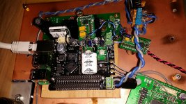
This is an early picture of Ians.
The new black adapter board for the Crystek XO's has 2 caps on the top and 7 under the board, different values top and bottom.
- Home
- Source & Line
- Digital Line Level
- Asynchronous I2S FIFO project, an ultimate weapon to fight the jitter