May be my question is still discussed here. I couldn't read 475 sites...
If I use Ians FIFO-project (need 8 channels input and output), use his LVDS , then there is the XO from the FIFO and a clock at the end of the line: DAC or DigitalAmp like I-AM-D.
Could someone please show me or link me to the way how to arrange a "one clock" soloution for this?
There could be a DAC - which? - (I would use 2x4 channels) or better something like the TI-Amp (above). Is there a Ian-DAC, timing with his FIFO-LVDS-project? Or how could this be down with an TI-Amp?
I didn't go deep into your project. But if it's just stereo application, you can bridge signals at multi-channel input to get more output groups.
It's just a thought.
Regards,
Ian
Ian, it is a little bit more difficult ")
I didn't read here about some years. But now I saw your work (...) that was the missing link for me ...
But I think you are not aware of the "other world of digital amps". Beginning at the time Tact/Lyngdorf was starting. Later Panasonic and others. Here at DIY-Forum the pendants. The heart is always TI! PWM to PCM. I2S is the way...
Why are these guys following this way - at the beginning spending much money for Tacts? After many years of "blowing away" experiences, if someone changed any caps, cables or something else in "analog" chains, these guys were getting tired of this stuff. Something basically is wrong, if you have a very experienced equipment and after changing a simple cable, everything has changed...
When Panasonic started with their TI versions (SA-XR ...) with high value the mod-freaks made all their things. But the maximum of these interventions changed also sound - but only a bit! No one is "blowing away" from these differences.
If I look at your work - the missing link - there could be after your LVDS/Fifo/MClock either a (TASxxxx) OR (a classical dac(+ x PS) + outputstage(+ x PS) + Amp(+ PS) + many different other stuff).
In other words: A short way and a very, very long way. If the long way needs linear power supply for the amp it is the worst possible efficiency at all.
But: May be the long and inefficient way could sound better... I am not really shure if that could be at all. For me: Still worth a try.
For you only important to know: At the moment this "other world" with its leastwise extremely short way is excluded from your stuff. Because every TI-chip is needing an extern XO with 12.288 MHz. May be I am wrong.
Here some links: TAS5558 and TAS5631B.
Last edited:
If I'm not mistaken, TAS5548 is aimed for economical home-theater applications. I couldn't imagine how difficult it would be to just manipulate jitters when they put ASRC, DAC, PLL, PWM all in one small chip. The cross-talk and interference between those sections and channels will be huge.
If I'm not mistaken, TAS5548 is aimed for economical home-theater applications. I couldn't imagine how difficult it would be to just manipulate jitters when they put ASRC, DAC, PLL, PWM all in one small chip. The cross-talk and interference between those sections and channels will be huge.
The both TI-chips are doing the job. Many of the special phenomena are conditioned by "long" ways. I2S i.e. is made only for short chip2chip distances. Problems occur because of the distance (-> LVDS). There are many advantages using "digital amps". Listen to a good equipment with high efficiency...
Last edited:
Here the link to the future. Ians McDualXO should work here as Masterclock. TAS3251 is still limited to 96 kHz.
DIY-Project with TAS3251
DIY-Project with TAS3251
To achieve higher performance and better sound quality, I finally decided to design my own FIFO for raspberry Pi based on my third generation FIFO technology.
I'd like FifoPi to have the following features and specifications:
1. Up to 768KHz full range I2S support;
2. DSD64,128,256,512,1024;
3. built-in 768KHz DoP decoder to enable RaspberryPi native DSD play back up to DSD256;
4. Isolator board will be included;
5. Clock board (isolated) will also be integrated, works with interchangeable XOs through standard sockets or adapters;
6. Supports full rang of XO frequencies from 11.2894 to 98.3040MHz;
7. Has two DC inputs for both isolated clean power and RaspberryPi power;
8. Has an additional non-isolated GPIO connector to make DAC controller working in isolated mode;
9. Works with good 5V linear power through on-board low noise LDO or pure direct 3.3V power from ulatr-capacitor or LifePO4 battery power supply;
10 Works with all RPi DAC HAT and external high-end DAC at synchronized master clock mode to remove jitter;
11. Optional external display panel with adjustable delay time;
12. DIY friendly with options and flexibility.
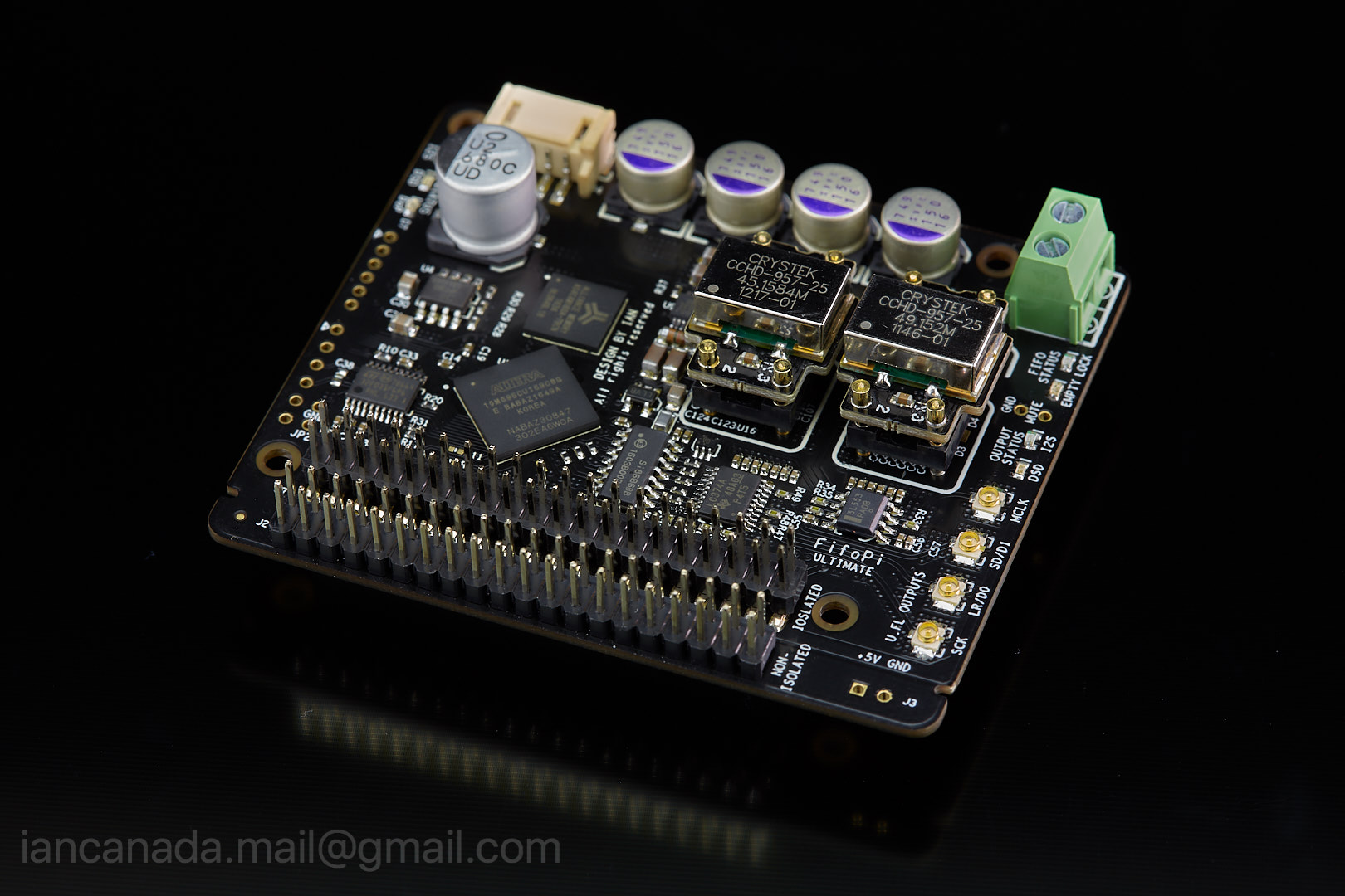
FifoPi_1 by Ian, on Flickr
Ian
Hi Ian,
I would like to use this board with external DAC board on AK4495SEQ.
Is it possible?
Guess I will need to change default XOs.
Can I order this board with XOs exactly needed for my DAC board?
If yes how I can do that? Is there an order form for that or something?
Or you can inform me about XOs parameters for my DAC board?
Thanks
Here is a link to DAC board:
Frss Shipping AK4495 SEQ II2S DAC decoder board (Upgrade function) купить на AliExpress
Frss Shipping AK4495 SEQ II2S DAC decoder board (Upgrade function) купить на AliExpress
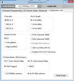
Amanero slave mod configeration
After some tinkering around I managed to connect Amanero to McFifo in slave MCLK mode.
Basics:
1. Flash Amanero with Slave_for_1080 for CPLD and firmware_1099c for CPU (or any other that suits your needs, e.g. DSD ones);
2. Set config bits: tick "Slave mode" and Pin 11 - 24.576 selector;
3. Put 49 MHz XO in XO2 socket of McFifo;
4. Connect 3.3V power from Amanero (pin 9 on Amanero) with 1K resistor to SLEN (pin 19 on J8 on McFifo);
5. Connect pin 11 on Amanero to XOSEL (pin 20 on J8 on McFifo);
6. Connect MLCK to one of SLAVE MCLK OUTPUT of McFIFO with u.fl cable;
7. Connect three I2S/DSD signals to McFIFO;
8. Set jumpers SLMCLKDIV0/2 (JP3 Open, JP4 Short) to divide McDual XO board XO frequencies to Amanero frequencies, if using 45/49 XOs. Please refer to McFifo manual for jumper settings in case you use another XO frequencies, Amanero accepts 22/24 only.
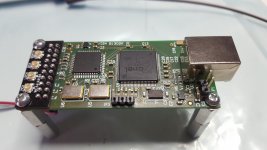
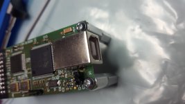
Also attaching some mods made to Amanero board:
1. USB power trace is cut next to USB connector;
2. External power connector is soldered directly on C2 before onboard reg;
3. External 5v power is fed from McFifo board;
4. Excellent uFL adapter made by Acko is soldered onto connector pin;
Attaching configuration bits and HW mod photos for your reference.
Music coming from this setup is simply great, no pops or clicks or whatsoever.
Forgot to mention: with sync USB-Fifo set-up sound coming from 9038 dacs is a bit cleaner than async one, although difference is marginal. All in all I would say that it is worth the effort of connecting 2 cables.
Thanks!
Daniil
After some tinkering around I managed to connect Amanero to McFifo in slave MCLK mode.
Basics:
1. Flash Amanero with Slave_for_1080 for CPLD and firmware_1099c for CPU (or any other that suits your needs, e.g. DSD ones);
2. Set config bits: tick "Slave mode" and Pin 11 - 24.576 selector;
3. Put 49 MHz XO in XO2 socket of McFifo;
4. Connect 3.3V power from Amanero (pin 9 on Amanero) with 1K resistor to SLEN (pin 19 on J8 on McFifo);
5. Connect pin 11 on Amanero to XOSEL (pin 20 on J8 on McFifo);
6. Connect MLCK to one of SLAVE MCLK OUTPUT of McFIFO with u.fl cable;
7. Connect three I2S/DSD signals to McFIFO;
8. Set jumpers SLMCLKDIV0/2 (JP3 Open, JP4 Short) to divide McDual XO board XO frequencies to Amanero frequencies, if using 45/49 XOs. Please refer to McFifo manual for jumper settings in case you use another XO frequencies, Amanero accepts 22/24 only.
Also attaching some mods made to Amanero board:
1. USB power trace is cut next to USB connector;
2. External power connector is soldered directly on C2 before onboard reg;
3. External 5v power is fed from McFifo board;
4. Excellent uFL adapter made by Acko is soldered onto connector pin;
Attaching configuration bits and HW mod photos for your reference.
Music coming from this setup is simply great, no pops or clicks or whatsoever.
Forgot to mention: with sync USB-Fifo set-up sound coming from 9038 dacs is a bit cleaner than async one, although difference is marginal. All in all I would say that it is worth the effort of connecting 2 cables.
Thanks!
Daniil
Attachments
Last edited:
Hi,I am trying to grasp what the benefits is from the FIFO approach vs a traditional approach where a DAC has a low-jitter clock? The HifiBerry DAC+ Pro is an example of that alternate approach.
The DAC+ Pro would act as an I2S Master and dictate the speed of the audio source. So, if the DAC+ Pro (or any similar DAC with a master clock) would have a really good XO, what is the benefit of the FIFO? In what way does it reduce jitter?
The DAC+ Pro would act as an I2S Master and dictate the speed of the audio source. So, if the DAC+ Pro (or any similar DAC with a master clock) would have a really good XO, what is the benefit of the FIFO? In what way does it reduce jitter?
Ian's FIFO allows you to try other clocks that could be better (or not), also provides galvanic isolation.
Also, not every source accepts external clocks and there are sources that introduce jitter even if the clock is the same so a FIFO that performs better would improve the result.
Ian's FIFO has clock dividers so if your source doesn't work with the HifiBerry clocks you can still use it.
Another advantage is it allows you to build a multi-channel, multi-input system by connecting multiple DACs and sources and have a common clock for all.
However, if you're happy with what you have right now it probably doesn't add much value
Is there any fact or evidence to this claim, that some sources introduce jitter even if clocked externally? That is the only point that is relevant according to the question as I can see. The other benefits of the Ian ecosystem I am clear about, i.e the isolator, different clocks boards etc which are great additions.Also, not every source accepts external clocks and there are sources that introduce jitter even if the clock is the same so a FIFO that performs better would improve the result.
Actually I came up with this idea of a FIFO on my own, when starting to consider a DAC diy project. Then I stumbled on Ian's work and realized it was all invented already.
And very well too!However, I also started to question my own idea when I realized how the I2S Master approach works. It combats the same problem in another way.
Last edited:
Is there any fact or evidence to this claim, that some sources introduce jitter even if clocked externally?
Honestly, I've only seen other people claim that, but have not seen any numbers.
However, if you look at the XMOS XUF216 datasheets you will notice that there is a PLL that is used to multiply an external clock to drive the chip cores which in turn generate the i2S signal. The datasheet says that extra care should be taken to separate the PLL power supply from the rest to ensure very clean power. My interpretation of that is that dirty power would affect the stability of the generated clock and thus the core execution frequency stability. That in turn will affect the quality of the I2S signal produced. And then, of course, there is the firmware part where bad programming could be starving the cores but I guess that's less of an issue since XMOS publishes reference implementation.
I would skip the FIFO if I could design an all-in-one board where I can control all the power supplies and placement of the elements, but I can't. I think I would have a better solution if I have different parts from different manufacturers by using a well designed FIFO board which also acts as the master clock.
The point of a FIFO is to cross clocking domains. No matter how accurate the clock of the FIFO is, in the end it is the DAC clock that determines the quality of the conversion. If you trust your DAC clock, and can slave the source to that, you don't need a FIFO, but if the source has an independent clock, the FIFO isolates the DAC side from the source clock.
The point of a FIFO is to cross clocking domains. No matter how accurate the clock of the FIFO is, in the end it is the DAC clock that determines the quality of the conversion. If you trust your DAC clock, and can slave the source to that, you don't need a FIFO, but if the source has an independent clock, the FIFO isolates the DAC side from the source clock.
Right, but I would like to add that the crucial signal in digital to analog conversion is the DAC word clock, so you should slave the FIFO to the latch of the DAC.
In other word you need a very good master clock at lower frequency as possible (around 5MHz with appropriate dividers) to feed directly the DAC latch enable, then a FIFO slaved to the Master clock.
My understanding is there are 2 different operating models re. jitter reduction methods;
1) Common method relies on DPLL, Digital Phase Locked Loop; essentially this brings the two clocks that are interfacing each other (e.g. dac and transport) into the same speed and you rely on the better one to minimise the deviation across that speed (jitter).
2) FIFO is different as it does not rely on the incoming data clock at all; it just buffers the data where original clock data is discarded. The only important thing is order of the data (hence the FIFO, First in First Out stack structure)
I believe, just the technology itself would not determine whether one method is superior than the other; it depends on many factors such as both phase noise and pullability of the clocks in the signal chain and PLL performance of the components. Yet, there is an ideal/sweet spot for a FIFO setting;
i) Having really very low phase noise clocks
ii) Running it in sync mode/master clock mode downstream to dac
In this way, one decouples himself from all the PLL stuff and clock phase/pullability performance across the signal chain
- Home
- Source & Line
- Digital Line Level
- Asynchronous I2S FIFO project, an ultimate weapon to fight the jitter