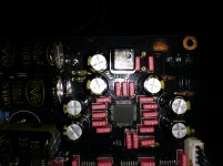
I don't think you need to sync up with the existing master clock as it essentially becomes the new master clock via the clock board.The i2s bus is just the connection between the usb, spdif, ect and the dac right? I know where these are located. Do I just latch the fifo onto here? Don't I have to ensure the fifo clock and the master clock are synced in some way?
Personally I wouldn't attempt such a mod without an oscilloscope.
Also condider power requirements if you're going to power FIFO from the onboard PSU.
But the dac module has a dedicated xo, how is it not going to interfere with the new clock of the fifo?I don't think you need to sync up with the existing master clock as it essentially becomes the new master clock via the clock board.
I have one, that's how I know where the i2s bus is, assuming the i2s bus is where the pwm signal is flowing from the input source to the dac pin.Personally I wouldn't attempt such a mod without an oscilloscope.
Actually there are a bunch of little buffer ICs between the source signals and the dac.
I'm going to use my own psu.Also condider power requirements if you're going to power FIFO from the onboard PSU.
if it's in fact enabled I'd question the benefits of FIFO in this application.
The audible benefits of the FIFO are not less apparent in the case of an async operated 9018.
Don't I have to ensure the fifo clock and the master clock are synced in some way?
You basically have two choices
- leave the 100MHz where it is and don't connect the master clock output of the fifo to the dac. The others signals go into the ugly white connector on your pics.
- desolder the crystal from the dac board and apply a MCK from the FiFO to the pad where the original crystal connects to the 9018. I2S signals again to ugly connector.
These two options will sound very different.
Ok, back to my earlier comment, where do the improvements come from when the FIFO is used with ESS chips if the data is SRCd and reclocked internally?The ESS chips have a sample rate converter at the input that decodes the data from any source (I2S or SPDIF) and converts it internally to its local clock, typically 100 MHz. You can defeat the SRC but not trivial.
Ok, back to my earlier comment, where do the improvements come from when the FIFO is used with ESS chips if the data is SRCd and reclocked internally?
How do we know there actually are improvements?
Ok, back to my earlier comment, where do the improvements come from when the FIFO is used with ESS chips if the data is SRCd and reclocked internally?
If you watch the internal DPLL status via I2C when you debug ESS Sabre32 DAC at real time. You will see it clearly.
When music is asynchronous with mclk, DPLL will keep turning to lock/trace the input frequency;
When music is synchronized with mclk, the DPLL will be in "free wheel" state without attempt to lock to any frequency. DPLL(ASRC) is bypassed automatically in sync mode.
Regards,
Ian
Last edited:
Thank you, this makes sense. But is it correct to say the benefits of FIFO are minimal if any at all if the ESS is run in async mode?
If MCLK is fed from FIFO, Sabre32 DAC will be always in sync mode, sound quality will get great improved in this case.
If only music signals are fed from FIFO with MCLK keeps local (100MHz for example), sound quality will still have some improvememt because DPLL runs at smaller bandwidth (you will see DPLL numbers are changing less in range than without FIFO) in this case. But the improvement will be not as much as feeding MCLK together at same time.
Regards,
Ian
Perfect, thank you.
I'm also curious how the FIFO recovers from a buffer overrun/underrun situation. I suspect it's pathological but there must be some reasonably safe way out, right?
It's not that terrible, my FiFO was designed to deal with the cases
When FIFO is full, the writing pointer will be jumped back to half depth. It's not easy to feel, but the music will be just short, for example, 0.1 second;
When FIFO is empty, the reading pointer will be jumped forward to half depth. The music will be just repeat, for example 0.1 second.
Though it doesn't affect listening experience much, but in real music playing back, it's not that easy to happen. Not only because it needs long time, but also because the internal management. So ,just no worry
Regards,
Ian
Last edited:
I have questions about connecting an Amanero to the FIFO.
I'm having some difficulty figuring out how to set up the "slave" mode
Also what do I do with the "slave jumpers" ?
It says to select between MCLK/1 MCLK/2 MCLK/4 MCLK/8 but makes no reference to what these are.
Lastly, do I really have to desolder the XOs from the Amanero?
I'm having some difficulty figuring out how to set up the "slave" mode
How do I drive SLEN high?Enable slave controlled MCLK mode by driving SLEN pin on J8 to logic high.
What is the "XO selection signal"?Connect XO selection signal from digital audio source to XOSEL pin on J8
Also what do I do with the "slave jumpers" ?
It says to select between MCLK/1 MCLK/2 MCLK/4 MCLK/8 but makes no reference to what these are.
Lastly, do I really have to desolder the XOs from the Amanero?
- Home
- Source & Line
- Digital Line Level
- Asynchronous I2S FIFO project, an ultimate weapon to fight the jitter
