Hi Ian,
I found the ref of the ldo smd reg I was talking about : http://www.analog.com/media/en/technical-documentation/data-sheets/ADM7151.pdf
From this thread : http://www.diyaudio.com/forums/power-supplies/253876-interested-adm7151-regulator.html#post3875013
Better spec, than the TS7A you was using till today; very little pin 8 smd (8 leads SOIC package) which can go directly near the crystals for the shortest path; simple 10 uF shunt cap at the output (less than the 5 x 10 uF of the TS7A reg= maybe easier & better to feed the crystals voltage)
COuld it be better for few dollars and directly embeded on the new clock board for a direct improvment ? Just asking, as you know not a high frequency ingener myself !
Thanks Eldam,
Yes, it's so far the best, I'll take into consideration.
Ian
Thanks Eldam,
Yes, it's so far the best, I'll take into consideration.
Ian
") Thanks for the thanks Ian,
Thanks for the thanks Ian,I'm just a non technician enthusiast but my motivation behind this asking is I know you always choose the best components for the SOUND : Crystek 957 or 950 crystals boards, even Pulsar Clock
 !
! The danger for most of us to use an external powersupply (even close 3 leads regs we could plug on the pcb) is to create more oscillations than a better expected result : each time it seems all those different powersupply regs need a different amount of capacitance/caps at their output to be stable : critic I assume for high frequencies (you are the knowledge man here ) !
Regs being cheaps, I believe your excellent designs deserve the best here (cause the layout and measurement is the biggest work you master yourself for using such very low noise SMD low drop regs !)
It is not for maybe 1 or 2 bucks by reg which should stop you to consider such choice ?!
The little experiment as an enthusiast I made on your last Clock II showed me the supply is very critic (at least with the Crystek 957: 44/48 M Hz)!Anyway, thank you for all your great work and sharing, I'm in for the batch to come, let's have a beer for tomorow saturday
 . Cheers.
I'm just a non technician enthusiast but my motivation behind this asking is I know you always choose the best components for the SOUND : Crystek 957 or 950 crystals boards, even Pulsar Clock
The danger for most of us to use an external powersupply (even close 3 leads regs we could plug on the pcb) is to create more oscillations than a better expected result : each time it seems all those different powersupply regs need a different amount of capacitance/caps at their output to be stable : critic I assume for high frequencies (you are the knowledge man here ) !
Regs being cheaps, I believe your excellent designs deserve the best here (cause the layout and measurement is the biggest work you master yourself for using such very low noise SMD low drop regs !)
It is not for maybe 1 or 2 bucks by reg which should stop you to consider such choice ?!
Anyway, thank you for all your great work and sharing, I'm in for the batch to come, let's have a beer for tomorow saturday
Thanks Eldam,
Cheers!
Ian
.... my goal is Q2 of this year
Hi Ian
This is great news. Thanks so much!
A multichannel FIFO is going to be a key link for some of us in achieving great sound using active digital crossovers with our old multibit TDA1541A/PCMXXX DACs. Up to now we've had to either use traditional crossovers or delta-sigma based DAC/processors. So Im excited.
I wonder if:
1. This USB to 8 channel XMOS board will be compatible to feed I2S to your new MC-FIFO?
XMOS Multichannel high-quality USB to/from I2S/DSD SPDIF PCB - DIYINHK
2. If clock timing will still be OK at different DACs if needing to add your PCM boards in after the MC-FIFO for supplying multibit DACs?
For example, would clocking still be OK using different PCM board setting with one PCM-board set to simultaneous mode for a TDA1541A DAC, a second PCM board doing PCM-right justified for a PCM63 DAC and a third DAC just needing straight I2S from the MC-FIFO.
I guess what Im asking is if one master clock can rule them all?
3. Some guys might want to run a fully active stereo pair of speakers 4m apart. The speakers would have multichannel active DACs and amps and only need power and multi-channel I2S in. So no speaker cables, no interconnects, no cross-overs. Do you think with careful coaxial or HDMI cabling the I2S out of the MC-FIFO could do 2m runs? I know everyone says I2S should be really short, like just 100mm maximum, but one guy ran I2S about 5m on just CAT5 cable around his room and reported great sound and no drop outs and that was just using the single ended I2S protocol, not the differential LVDS protocol.
"It is important to understand, that I2S signaling was developed at first to be used internally in DACs (and CDPs), as the signal is single ended and can degrade over distance. BUT, the I2S signaling used externally by the Sonore Signature Rendu is known as LVDS, this is a balanced version of I2S (so 4 signals running on 4 twisted pairs of wires which are balanced) and does not degrade over normal interconnect distances (a meter or two). An HDMI cable is used because there are good, high bandwidth HDMI cables with the proper impedance and enough twisted pairs. ." Barrows 2015
Last edited:
MC FIFO and MC XO power req
Hi Ian,
With the large thirst we're waiting the realization of the new boards.
1) Are such power requirements for the new MC FIFO and MC XO?
2) Does it possible (and reasonable)) use TCXO type Oscillators on MC Clock board? Does it compatible with them?
Thank you again for sharing such fine solutions!
Alex
Thanks Alex,
1. The MC FIFO will be around 150mA @90.xxx/98.xxx, while the MC clock board will be around 120mA when run 8 channels together at same frequency range plus power consumption of two XOs.
2. TCXO would be fine, But OCXO can be even better. The most important thing for a audio XO is the phase noise not the ppm.
Regards,
Ian
Thank you, Ian for explanation!
especially about OCXO
There are kind of internal signal in the MC FIFO which we will be able to use as drive signal for the DSD/PCM mode switch of AK4495/97 DAC? I mean DSD/PCM detection.
This will be kind of solution for non-automatic DACs.
Thank you, Ian for explanation!
especially about OCXO
There are kind of internal signal in the MC FIFO which we will be able to use as drive signal for the DSD/PCM mode switch of AK4495/97 DAC? I mean DSD/PCM detection.
This will be kind of solution for non-automatic DACs.
Thanks surfchampion, that a very good point.
There will be a active high signal called DSD to indicate DSD format, just for DACs without DSD/I2S auto-detect function. This signal will also be isolated.
Ian
Thanks Eldam,
Yes, it's so far the best, I'll take into consideration.
Ian
I would be happy if you just made another board for ADM7151 regulator, so people could buy either the TPS or the ADM if they want to..
But i totally understand if you for simplicity want to go with only one regulator board, rather than two..
Hi Ian,
I really need your help. I bought a FIFO v1 board, a SI570 reclock board and SPDIF interface board from fellow members here. But when I use the FIFO board with my Raspberry Pi 3, a problem happens: The D7 LED is ON, which from I read in the documentation indicates that the FIFO is empty. I have try several methods, changing i2s driver (Hifiberry DAC, DAC+, Digi+, ian FIFOII) from Moode Audio, changing cable from Rpi to FIFO board but the problem is still there.
I hope you can help me with this situation. This is because I do something wrong on set up or just because FIFO v1 is not compatible with Raspberry Pi i2s signal?
Best regards,
Mai
An externally hosted image should be here but it was not working when we last tested it.
Last edited:
Hi Ian,
I really need your help. I bought a FIFO v1 board, a SI570 reclock board and SPDIF interface board from fellow members here. But when I use the FIFO board with my Raspberry Pi 3, a problem happens: The D7 LED is ON, which from I read in the documentation indicates that the FIFO is empty. I have try several methods, changing i2s driver (Hifiberry DAC, DAC+, Digi+, ian FIFOII) from Moode Audio, changing cable from Rpi to FIFO board but the problem is still there.
I hope you can help me with this situation. This is because I do something wrong on set up or just because FIFO v1 is not compatible with Raspberry Pi i2s signal?
Best regards,
Mai
Hi,
No worry. It seems FIFO didn't receive correct I2S signals from RPi.
1. Use a RPi DAC HAT just to confirm RPi and player work together generating correct I2S signals;
2. If 1 is good, refer the schematic below to confirm your connections are correct, or use a RPi I2S adapter to get good connections in between.
Good luck.
Ian
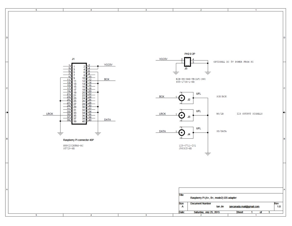 SchematicOfRaspberryPiI2S by Ian, on Flickr
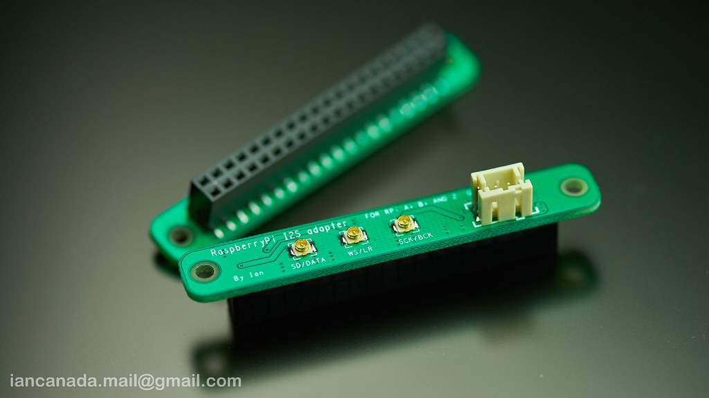 PaspberryPiI2SPCBAssembled1 by Ian, on Flickr
@ RollE2K: ... mine (proposal) was more to choose the best for a better "on board" regulation with the good amount of capacitance for the clock !
ADM7151 is not rare, for instance here on DIYUDIO, JLSOUNDS uses it in its last AK4595 DAC ! AK4495 - I2S over USB Audio
why putt or choose a Crystek but not the best regs ... but on a more costy outside board option ?!
If it's to give choice for DIY, it will be funnier to challenge one of the best smd reg than the regular old one : ldo lp5900sd-3.3/nopb of the Ian's boards ?
optional PS board is near 25 % of the cost of the main board ! If it's about money & cost production, my feeling is it's better to charge more but to putt all on the main board !
I'm not technician but why not an embeded smd diodes bridge + snubber + adm7151 or the ldo which is best for a clock with the good amount of caps after ???
Ok, a jumper for the ones whom prefer A123 cell, shunt PS, etc !
I believe it's critic mainly for the clock board with the high Fhz of the crystals > 50 M Hz for the new ESS or AK dac chips.
I'm sure in regards to the quality of the Ian's boards, most of us should be ready to pay a little more and have just the pleasure to plug directly a R-Core transformer for instance ! Anyway, the jumpers to short the main PS entry is always a good idea than Ian offers to us for alternativ tweakings !
My worry here is we play with high frequencies and most of us are not able to measure it on a clock board ! Ian has the best equipments and knowledge to do it for us once ?!
But maybe it's not mandatory for clock quality ? Ian, does it change thing at ears with the tests you made on the TDA1541A or the ESS9016 you have please ?
Eldam
Last edited:
Hi,
No worry. It seems FIFO didn't receive correct I2S signals from RPi.
1. Use a RPi DAC HAT just to confirm RPi and player work together generating correct I2S signals;
2. If 1 is good, refer the schematic below to confirm your connections are correct, or use a RPi I2S adapter to get good connections in between.
Good luck.
Ian
Hi Ian,
many thanks for your help. As for connection, I follow strictly to your guide in post below, so I think there is no mistake here.
http://www.diyaudio.com/forums/digi...project-ultimate-weapon-fight-jitter-360.html
I don't have any RPI DAC HAT but I will buy one to check.
Best regards,
Mai
Hi Ian,
I really need your help. I bought a FIFO v1 board, a SI570 reclock board and SPDIF interface board from fellow members here. But when I use the FIFO board with my Raspberry Pi 3, a problem happens: The D7 LED is ON, which from I read in the documentation indicates that the FIFO is empty. I have try several methods, changing i2s driver (Hifiberry DAC, DAC+, Digi+, ian FIFOII) from Moode Audio, changing cable from Rpi to FIFO board but the problem is still there.
I hope you can help me with this situation. This is because I do something wrong on set up or just because FIFO v1 is not compatible with Raspberry Pi i2s signal?
Best regards,
Mai
What Ian said, plus it looks to me like your I2S signal cables are way too long.
Hi All,
Just a question on the 3.3v power for the clock board oscillators. I presume I dont need to implement a 3.3v regulator on the board if I am feeding the signal from external oscillator boards that already have their own 3.3 supply (ie. Well Tempered Master Clock boards)? I would obviously still power the main clock board with the 5-6Vdc but can I just leave off the 3.3V LDO reg?
Just a question on the 3.3v power for the clock board oscillators. I presume I dont need to implement a 3.3v regulator on the board if I am feeding the signal from external oscillator boards that already have their own 3.3 supply (ie. Well Tempered Master Clock boards)? I would obviously still power the main clock board with the 5-6Vdc but can I just leave off the 3.3V LDO reg?
Hi Ian,
Just one question on the variable time delay the new MC FIFO will implement. Will it allow for no delay ? ie. similar to pass through?
Many thanks for your excellent product.
Abraham.
Hi Abraham,
I've already placed a production order for both MC FIFO and MC Dual XO on last weekend.
Hopefully I can get them at the end of this month. But I'm not hurry. Quality is always my first priority.
It will be available very soon
Ian
Hi,
My new FIFO has 256Mb memory, not 4Mb.
The buffer on USB interface is only for communication, has nothing to do with the sound quality. The problem of USB streamer is the high jitter level.
Why FIFO can improve sound quality? It's not because of buffering. The key reason is clock replacement.
Regards,
Ian
The buffer should be with the sound quality. In Raspberry Pi, CPU read data from the RAM, it will be intermittent, so if the buffer is in the board, it will be able to effectively solve the CPU read intermittent jitter. Perhaps the problem lies in the existing model, failed to use the buffer to effectively solve the CPU read intermittent jitter. I'm not so sure.
The buffer should be with the sound quality. In Raspberry Pi, CPU read data from the RAM, it will be intermittent, so if the buffer is in the board, it will be able to effectively solve the CPU read intermittent jitter. Perhaps the problem lies in the existing model, failed to use the buffer to effectively solve the CPU read intermittent jitter. I'm not so sure.
@ cyrilliu,
If you get chance watching the I2S signal from a RPi by a oscilloscope higher than 1GHz bandwidth, you will know how much the jitter that a RPi outputs is. That jitter comes from the internal audio clock generator/PLL. Has nothing to do with the buffer size. No matter how big the internal buffer is, that jitter will keep same and can not be eliminated. That's why I said RPi internal data buffer has nothing to do with sound quality. It's only has something to do with function.
FIFO is totally different story. FIFO is a data buffer between two clock domain. The goal of a FIFO is to deal with tolerances between clocks. FIFO itself doesn't improve sound quality. But with a FIFO, a poor RPi clock can be replaced by a good clock without affecting any to the music data. A poor signal is become a very high quality signal after FIFO. That the principle of FIFO.
Regards,
Ian
- Home
- Source & Line
- Digital Line Level
- Asynchronous I2S FIFO project, an ultimate weapon to fight the jitter