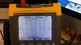
384Khz
I am only six and a half foot tall and short of brain, so this counts for me too!
One time our Guru says it works, another time the opposite.
The thing I know, by trying, is that I can not manage higher than 192 with the dual board + 45/49 and the 1794 DDDac. But it can with the 570 board.
Think I have to go back to school.....or find me some fresh braincells.
Now back to the music,
have a nice sunny weekend,
Ed
Thanks for trying this, Ed.
Even if nothing different happens, how can it not change anything?. This is all way over my head BTW.
Regards,
Shane
I am only six and a half foot tall and short of brain, so this counts for me too!
One time our Guru says it works, another time the opposite.
The thing I know, by trying, is that I can not manage higher than 192 with the dual board + 45/49 and the 1794 DDDac. But it can with the 570 board.
Think I have to go back to school.....or find me some fresh braincells.
Now back to the music,
have a nice sunny weekend,
Ed
384Khz
Sorry, it is only five feet and seven inches!
Ed
I am only six and a half foot ........
Sorry, it is only five feet and seven inches!
Ed
Sorry, it is only five feet and seven inches!
Ed
Ed, its not considered cheating if you leave your shoes on

sorry for maybe dump question, but i spent several hours reading and did not figure out following... if i am using SINGLE good master clock located at the DAC board to drive DAC chip and then route it to USB->I2S board which is located close to DAC board (short cables) why do i need that buffer? i should not have any jitter which is more than my primary MCLK jitter itself as everything happens in sync and driven by the only one oscillator. What am i missing?
sorry for maybe dump question, but i spent several hours reading and did not figure out following... if i am using SINGLE good master clock located at the DAC board to drive DAC chip and then route it to USB->I2S board which is located close to DAC board (short cables) why do i need that buffer? i should not have any jitter which is more than my primary MCLK jitter itself as everything happens in sync and driven by the only one oscillator. What am i missing?
Good point, I said so several times in this thread.
Place a very low noise master clock close to the DAC, then send it back to the source.
In the case of the FIFO buffer it means using the same MCLK of the DAC, removing the reclock board from the FIFO buffer.
You don't need to send the MCLK to the device before the FIFO buffer, since it work as an ASRC, isolating from the previous device.
My master clock is almost ready (I'm waiting for the PCB), if you are interested I'll open a thread soon.
Right, i do understand the purpose of the FIFO buffer as bit-perfect isolator but i see no real reason of it with common master clock.. There is also external dual XO board, but disadvantages of the MCLK connection,wires and everything seems more than locating oscillator right near the dac chip and remove all extra boards which actually adds jitter to MCLK bus by itself...
Good point, I said so several times in this thread.
Place a very low noise master clock close to the DAC, then send it back to the source.
In the case of the FIFO buffer it means using the same MCLK of the DAC, removing the reclock board from the FIFO buffer.
You don't need to send the MCLK to the device before the FIFO buffer, since it work as an ASRC, isolating from the previous device.
My master clock is almost ready (I'm waiting for the PCB), if you are interested I'll open a thread soon.
Hi Ian,
Before sending the board to you, I thought that possibly my power supply feeding the Dual Clock board and one half of the isolator was not supplying enough current since there is a CCS in the power supply.
To check the Chrystek 45MHz xo, I tried the 45/24 combination and it worked. So both Chrystek xo frequencies are working properly.
I then upped the CCS current from 70 mA to 120 mA and tried the board with both Chrystek XOs in place and again, the leds did not light up. According to the Chrystek data sheet, the XO draws a maximum of 25 mA and I have increased the current available by 50 mA to accommodate the second Chrystek XO. Is 120 mA enough for the Dual clock board with Chrystek CCHD 957 XOs plus one half of the isolator? Or is there something else that I am missing?
Thanks for your help.
Ben
Hi Ian,
Success at last. The last time I posted, I had determined that the Chrystek XOs were ok.
After thinking about it some more, I checked the supply voltage with both Chrysteks in place. The voltage had sagged to below 3v. I then checked the data sheet for the isolators and it appears that the current requirement for them increases with frequency.
I then upped the ccs current from 125 ma to 175 ma and that did the trick. So it appears that for the Dual Clock board with Chrystek CCHD 957 XOs of 45 and 49 MHz and also powering the isolator board, the minimum current requirement at 5v is somewhere between 125 and 175 ma.
Ben
Attachments
Right, i do understand the purpose of the FIFO buffer as bit-perfect isolator but i see no real reason of it with common master clock.. There is also external dual XO board, but disadvantages of the MCLK connection,wires and everything seems more than locating oscillator right near the dac chip and remove all extra boards which actually adds jitter to MCLK bus by itself...
The reason to use the FIFO buffer (without the reclocking board) is that it isolates the DAC from the source, avoiding the propagation of the source jitter (sending back the MCLK of the DAC to the FIFO).
If you can sync the source directly from the DAC there is no reason to add more extra circuits.
Hi Ian,
Success at last. The last time I posted, I had determined that the Chrystek XOs were ok.
After thinking about it some more, I checked the supply voltage with both Chrysteks in place. The voltage had sagged to below 3v. I then checked the data sheet for the isolators and it appears that the current requirement for them increases with frequency.
I then upped the ccs current from 125 ma to 175 ma and that did the trick. So it appears that for the Dual Clock board with Chrystek CCHD 957 XOs of 45 and 49 MHz and also powering the isolator board, the minimum current requirement at 5v is somewhere between 125 and 175 ma.
Ben
Hi Ben,
Good to know you figure out the issue. I didn't realize ccs current can cause xo stop working. Thank you for sharing your experience with others.
BTW. I like your project, the logic looks very clear
.Have a nice weekend,
Ian
Hi Ian,
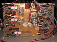
I tried to keep the wires short between the clock/pcm/dac boards so that was what worked best.
The dac is tda1541a on a copper foiled Veroboard, based on Thorsten Loesch's many posts regarding the subject a few years ago, plus also using ideas from John of ecdesigns and others. It used to have reclocking and dem clocking on the board but with the addition of your pcm board, that has been removed and their power supplies power the dual clock and pcm boards.
The addition of your boards have made a big difference in the sound, all for the better.
Ben
Attachments
Applying DPLL No Bandwidth Setting on ES9018
I assume many users of FIFO connect their ES9018 DACs to the FIFOs in a synchronous master clocking scheme.
Recently, I tried "No Bandwidth Setting" with my SDTrans & Chiaki's DAC and had a very good result, more smoother sound than that of "The Lowest Setting". I'd like to recommend some FIFO+ES9018 users try the setting.
However, here is a certain limitation and you can't always apply the setting.
The "No Bandwidth" is only applicable when a synchronous master clock MCLK frequency is four times of BCLK/DSD CLK frequency. Even on this condition, you will suffer periodic unlock events.
In my case, 174.6/192 kHz PCM or DSD256 sources can be played with 45.1584 or 49.152 MHz synchronous master clock generated by OCXOs.
Whats the best reclock option out there ?
Hello every one , i am brand new on the forum .
Can some one help me to get the best reclock for the DIYINHK usb latest board for the es9018k2 dac.
the whole kitt looks well build , for now i wait on the 10 x 4uV noise voltage regulators .
Ted smith who made directstream told some good info on PSU and jitter en DSD.
noise must be less than 1/1000000 for 3,3V thats 3,3uV / 1,8V thats 1.8uV
Jitter is a real pain in the budd specialy with high sample speeds it boost the jitter big time every step up. 6dB each step Ted say in one of the you tubes .
One of the best tricks is to reclock it , like the Ian’s FIFO Jitter eliminator however it won`t play dsd dsx i think but it goes to 24Bits 192KHz very low jitter .
The latest DIYINHK XMOS have a X out for the reclocking .
Can` t wait till DIYINHK will bring a reclocker board that will do all pcm and perhaps dsd ect.
The perfect bit volume is very cool indeed .
Can someone tell me how to do the reclocking on the DIYINHK USB board ?
I might post as well in the Ian’s FIFO Jitter eliminator forum to see if there are is some info . even don` t know if Ian still sell the Ian’s FIFO Jitter eliminator.
Here is the old link for the DC DC kill in the X mos http://www.diyaudio.com/forums/digital-source/233926-new-xmos-usb-384khz-15.html
before you might do it on the new type USB look to this photo and data . http://www.squarewave.co.uk/SWT_pages/SWT_images/IMG_5487s.JPG
http://www.xmos.com/download/public/XS1-U8A-64-FB96-Datasheet(X6319D).pdf
GTL nice posting on H i F i D U I N O | Lot of Value, Little Money looks great for never ending DIY . well done .
there more USB cards out there like Luckit | Audiophile grade DIY products and http://www.diyaudio.com/forums/digital-source/236028-xmos-dsd-384-khz-32bit-usb.html
and Amanero Technologies
I am a analog guy so please help me with the digital side how to reclock best way .
I know how to build one of the world best I/V tube stage but don` t ask me about digital stuff hihi .
Ted smith who made directstream told us why the older PCM board might be better than the new DSD PCM combo` s due to the jitter of the clock ,dac chip disign no real 1 bit ect. however clocks can be bought thats easy but the right reclock HQ is the best way otherwise we will stuck with less preformance like most old dac as well the clocks at lower freq. have much lower phase noise easy.
For that reason many will stick or go back to there PCM decks . with 192Khz top or less. see the Ian’s FIFO Jitter eliminator they all love the SPDIF + reclock boards for the R2 dacs .
However i want to stick with ESS for now the 9018k2 can sound very good if done all right . The DIYINHK es9018k2 have a SPDIF in as well .
One problem not much look in to is the Ground loops we all make PSU` s low noise ect . very nice however with the PSU kits and the dac kits boards have common ground so only ONE GND is enough than one must be good and short . best is to use strap copper min. 1/3 wide of the total length .
Perhaps one best option is a PSU PCB with space cut out for fit in the DIY boards and connect the GND with one copper strap to each board or around the boards so much GND as possible .
PSU wires long are antenna ` s and pick up things like clocks .
and wire next to each other have inductance and capacitance .
As well the UBS I2S to the DAC is to long less than a one inch is better .
The DIYINHK is 2 inch not too bad at all .
Just shorten the flat cables a bit and perhaps not use any GND connection in that i2s to dac in a flat cable as the GND is on the copper strap around the board to one big GND plane .
So please help me with the reclocking DIYINK or someone else can give tips whats best to do so far . .
I will post my I/V tube transformer stage later on if there is good feedback on how to reclock the DIYINHK or other USB boards .
good luck to all .
John (the netherlands)
Astronod,
your questions seem near than mines : http://www.diyaudio.com/forums/digi...nderstanding-non-specialists.html#post3971657
your questions seem near than mines : http://www.diyaudio.com/forums/digi...nderstanding-non-specialists.html#post3971657
Running FIFO at 384KHz with Dual XO clock board and 45/49 MHz XO on TDA1541A
@ed linssen
I’m so sorry for the long time delay addressing your problem.
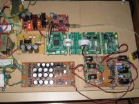
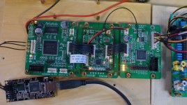
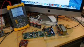
I set up a testing fixture today running at 384KHz without problem.
My configuration is:
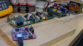
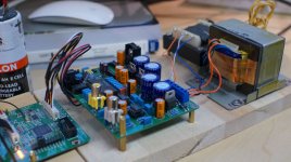
iMac - USB – FIFO – DualXO(45/49) – PCM board – TDA1541A DAC
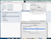
Please see the pictures for the jumpers of the PCM board and other details
1. With Amanero Combo384 USB and u.fl cables, it’s running perfect from 88.2KHz to 384KHz.
2. With WaweIO XMOS USB(upgraded to 384KHZ FW) and u.fl cables without isolator, it’s also running perfect from 88.2KHz to 384KHz.
3. With WaweIO XMOS USB(upgraded to 384KHZ FW) and with isolator, it could only run up to 192KHz. Noise starts from 352KHz and gets worth at 384KHz. Maybe that’s your case. I don’t know why. I suspect the speed of IL715-3 is not enough, but I have no time to analyze the waveform by my 1GHz oscilloscope.
Some tips for 384KHz:
1. Use u.fl coaxial cables or twisted pair as possible as you can if it’s longer than 2 inches, the BCK(SCK) will run at 24.576MHz in this case.
2. If want to use isolator after USB, please try hi-speed version, for example, 150MHz data rate.
Please let me know if there is any help solving the problem.
Thanks Palmito, Thanks Ceglar for your helps.
Have a good weekend.
Ian
Works perfect without MCK from Wavio I2s/Spdif-Fifo/clock/Dac.
1) Dual clockboard with 45 and 49 clocks up to 192 Khz.
2) 570 clockboard up to 384!
3) For single clock board I did not try higher F than 48Khz.
Regards,
Ed
@ed linssen
I’m so sorry for the long time delay addressing your problem.
I set up a testing fixture today running at 384KHz without problem.
My configuration is:
iMac - USB – FIFO – DualXO(45/49) – PCM board – TDA1541A DAC
Please see the pictures for the jumpers of the PCM board and other details
1. With Amanero Combo384 USB and u.fl cables, it’s running perfect from 88.2KHz to 384KHz.
2. With WaweIO XMOS USB(upgraded to 384KHZ FW) and u.fl cables without isolator, it’s also running perfect from 88.2KHz to 384KHz.
3. With WaweIO XMOS USB(upgraded to 384KHZ FW) and with isolator, it could only run up to 192KHz. Noise starts from 352KHz and gets worth at 384KHz. Maybe that’s your case. I don’t know why. I suspect the speed of IL715-3 is not enough, but I have no time to analyze the waveform by my 1GHz oscilloscope.
Some tips for 384KHz:
1. Use u.fl coaxial cables or twisted pair as possible as you can if it’s longer than 2 inches, the BCK(SCK) will run at 24.576MHz in this case.
2. If want to use isolator after USB, please try hi-speed version, for example, 150MHz data rate.
Please let me know if there is any help solving the problem.
Thanks Palmito, Thanks Ceglar for your helps.
Have a good weekend.
Ian
Attachments
-
 DSC05010S.jpg154.2 KB · Views: 812
 -
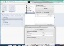
 Screen Shot 2014-08-02 at 5.19.48 PM.png379.1 KB · Views: 800
 -
 DSC05006S.jpg89.1 KB · Views: 776
 -
 Screen Shot 2014-08-02 at 5.15.45 PM.png411.8 KB · Views: 697
 -
 DSC05007S.jpg121.9 KB · Views: 690
 -
 DSC05012S.jpg119.4 KB · Views: 314
 -
 DSC05014S.jpg91 KB · Views: 315
Last edited:
your response 4011113]@ed linssen
Thank you Ian for again diving into this problem I have in playing in >192 res.
while using Dual XO board with 45/49 clocks!
I must state I don't have the TDA1541 dac and do not own the PCM-board.
My Dac is a 1794. (DDDAC1794)
But the basic set up is as in your setup 3.
Only, I use the isolated connection from the WaveIO, going to the 'backdoor'
of the SPDIF-board and than to Fifo>Isolator>clockboard>Dac.
You suggested that the bandwith of the isolator-board could be the culprit.
Though I can play any Freq. with the 570 clockboard, isolator-board included,
I can only go as high as 192KHZ when using the dual-clockboard!
So I took out the Isolator-board and gess what, the system works on any Frequency again!
The isolator used on my board is:SI8650.
End of this story is that all works now but I can not use this Isolator in this setup.
Maybe there is a suggestion for another isolator/chip.
But I am really glad, I am a big step ahead,
Thanks for all the help to all of you,
Ed
@ed linssen
I’m so sorry for the long time delay addressing your problem.
I set up a testing fixture today running at 384KHz without problem.
My configuration is:
iMac - USB – FIFO – DualXO(45/49) – PCM board – TDA1541A DAC
Please see the pictures for the jumpers of the PCM board and other details
1. With Amanero Combo384 USB and u.fl cables, it’s running perfect from 88.2KHz to 384KHz.
2. With WaweIO XMOS USB(upgraded to 384KHZ FW) and u.fl cables without isolator, it’s also running perfect from 88.2KHz to 384KHz.
3. With WaweIO XMOS USB(upgraded to 384KHZ FW) and with isolator, it could only run up to 192KHz. Noise starts from 352KHz and gets worth at 384KHz. Maybe that’s your case. I don’t know why. I suspect the speed of IL715-3 is not enough, but I have no time to analyze the waveform by my 1GHz oscilloscope.
Some tips for 384KHz:
1. Use u.fl coaxial cables or twisted pair as possible as you can if it’s longer than 2 inches, the BCK(SCK) will run at 24.576MHz in this case.
2. If want to use isolator after USB, please try hi-speed version, for example, 150MHz data rate.
Please let me know if there is any help solving the problem.
Thanks Palmito, Thanks Ceglar for your helps.
Have a good weekend.
Ian
Thank you Ian for again diving into this problem I have in playing in >192 res.
while using Dual XO board with 45/49 clocks!
I must state I don't have the TDA1541 dac and do not own the PCM-board.
My Dac is a 1794. (DDDAC1794)
But the basic set up is as in your setup 3.
Only, I use the isolated connection from the WaveIO, going to the 'backdoor'
of the SPDIF-board and than to Fifo>Isolator>clockboard>Dac.
You suggested that the bandwith of the isolator-board could be the culprit.
Though I can play any Freq. with the 570 clockboard, isolator-board included,
I can only go as high as 192KHZ when using the dual-clockboard!
So I took out the Isolator-board and gess what, the system works on any Frequency again!
The isolator used on my board is:SI8650.
End of this story is that all works now but I can not use this Isolator in this setup.
Maybe there is a suggestion for another isolator/chip.
But I am really glad, I am a big step ahead,
Thanks for all the help to all of you,
Ed
Thank you Ian for again diving into this problem I have in playing in >192 res.
So I took out the Isolator-board and guess what, the system works on any Frequency again!
The isolator used on my board is:SI8650.
End of this story is that all works now but I can not use this Isolator in this setup.
Maybe there is a suggestion for another isolator/chip.
But I am really glad, I am a big step ahead,
Thanks for all the help to all of you,
Ed
Regettably I have to put the isolator-board back in place, because I modified the dualclock board to be fed by a lifepo4 battery and thus feeding two supplies linked. Little Fifo does not like that!
So for the time being everything back to the 'old' situation. (not able to play higher res. than 192Khz)
At least I know now, where the problem comes from.
Regards,
Ed
Last edited:
Dual clockboard/384Khz
Hi Ian,
Can I, after removing L11 on the dualXO clockboard, and as suggested by you, after removing the two regs on the board, feed J5 with the lifepo4 without useing the isolator board? And not killing the Fifo?
I thought I read this somewhere.
Thanks,
regards,
Ed
Regettably I have to put the isolator-board back in place, because I modified the dualclock board to be fed by a lifepo4 battery and thus feeding two supplies linked. Little Fifo does not like that!
So for the time being everything back to the 'old' situation. (not able to play higher res. than 192Khz)
At least I know now, where the problem comes from.
Regards,
Ed
Hi Ian,
Can I, after removing L11 on the dualXO clockboard, and as suggested by you, after removing the two regs on the board, feed J5 with the lifepo4 without useing the isolator board? And not killing the Fifo?
I thought I read this somewhere.
Thanks,
regards,
Ed
2. With WaweIO XMOS USB(upgraded to 384KHZ FW) and u.fl cables without isolator, it’s also running perfect from 88.2KHz to 384KHz.
3. With WaweIO XMOS USB(upgraded to 384KHZ FW) and with isolator, it could only run up to 192KHz. Noise starts from 352KHz and gets worth at 384KHz. Maybe that’s your case. I don’t know why. I suspect the speed of IL715-3 is not enough, but I have no time to analyze the waveform by my 1GHz oscilloscope.
Thanks, Ian.
The IL715 is the same isolator chip used on the WaveIO.. seems odd that they'd upgrade the firmware for use at 384k if the isolator chip wasn't up to task?. Then again, stranger things have happened.
Shane
Dual clockboard/384Khz
Hi Shane,
I wonder then, why is it, when I use the isolated output from the WaveIO going straight (without Ian's isolator board) into the Fifo, I can play 384 files without problems?
Ed
Thanks, Ian.
The IL715 is the same isolator chip used on the WaveIO.. seems odd that they'd upgrade the firmware for use at 384k if the isolator chip wasn't up to task?. Then again, stranger things have happened.
Shane
Hi Shane,
I wonder then, why is it, when I use the isolated output from the WaveIO going straight (without Ian's isolator board) into the Fifo, I can play 384 files without problems?
Ed
- Home
- Source & Line
- Digital Line Level
- Asynchronous I2S FIFO project, an ultimate weapon to fight the jitter