I believe as Ian has noted re: capacitors/Si570, much of what we're hearing (at this level) are component choices. Amazing really. That's my subjective sense; I have no means of measuring the jitter of each clock board. But I am sonically sensitive to the effects of jitter. That tells me these two are very close, with the dual clock board being very slightly better. When I supply the Si570 via battery, I expect to close that (very small) gap.
either permutation is so superior to anything our ears have ever heard with regard to jitter performance it just amazes me that you are hearing differences. I mean at this level, jitter should be completely out of the question. Very odd. Makes me think oscillation/intererfance or some other rf phenomenom is occuring.
Hi regal,
Yes, that's very interesting. I might be wrong, But I think jitter is very similar to FM modulation. MCLK is the carry frequency. Even we got same jitter level from different clock, as if the same amplitude of the modulating signal, but the modulating signal itself may different, for example, music and news are different, even different music.
We are more focus on the jitter numbers. But few people is talking about the characteristics or properties of jitter itself. I believe that really making difference.
Have a nice weekend.
Ian
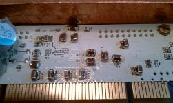
After a long day listening I came to the conclusion that I dont like MLCC caps at the TPS output reg. They give some artifacts to sound. So just replaced 4x10uF MLCC with 10x1 uF/63 film caps. They does not fit on the board ofc, but I very like changes in sound. Midrange and highs are clear and sweet now, huge soundstage, nothing annoys me so far. The best setup for me since got fifo kit.
I believe as Ian has noted re: capacitors/Si570, much of what we're hearing (at this level) are component choices. Amazing really. That's my subjective sense; I have no means of measuring the jitter of each clock board. But I am sonically sensitive to the effects of jitter. That tells me these two are very close, with the dual clock board being very slightly better. When I supply the Si570 via battery, I expect to close that (very small) gap.
After installing the fifo, I figured that component changes not only around the clock and the fifo is much more audible, but everywhere, as well in the i/v conversion and tube output stage. The fifo brought me a huge step forward to understand where in my setup are the remaining mistakes....the impression of realismn, transparency and attitudes which I knew only from big, heavy turntables before.
Hi , i`ve got problem (?) - with BIIISE in synchronous mode +FIFO,isolator,Si_XO board output level (analog) is much lower . In asynchronous mode everything is OK.... the sound in synchro mode is rather "thin" , it lacks "body" . anybody else ?
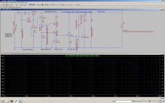
I suspect BIII SE - it looks like this : Buffalo2-Sabre32 DAC MEGA Test | H i F i D U I N O (1 test result) ...
I suspect BIII SE - it looks like this : Buffalo2-Sabre32 DAC MEGA Test | H i F i D U I N O (1 test result) ...
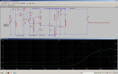
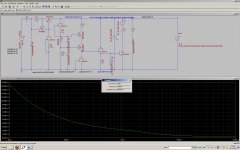
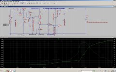
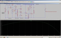
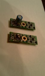
It's fascinating how Si board is sensitive to power regs ") In my last setup I am using single Kemet polymer cap 100u/16v and it's best option so far. While testing TPS board i want build "Salas style" local shunt. Initial sims are promising. Iam using Kemet caps models.
In my last setup I am using single Kemet polymer cap 100u/16v and it's best option so far. While testing TPS board i want build "Salas style" local shunt. Initial sims are promising. Iam using Kemet caps models.
In my last setup I am using single Kemet polymer cap 100u/16v and it's best option so far. While testing TPS board i want build "Salas style" local shunt. Initial sims are promising. Iam using Kemet caps models.Attachments
Hi , i`ve got problem (?) - with BIIISE in synchronous mode +FIFO,isolator,Si_XO board output level (analog) is much lower . In asynchronous mode everything is OK....
Are you using the MCU on board TPA Buffalo III SE? How is your power on sequence? Before you turn power of BIIISE on, your synchronous master clock must be supplied to the ES9018 device so that the chip can receive initial register setting commands sent from MCU via internal I2C bus. Otherwise, ES9018 starts with its hardware defaults that lack input redirections.
In the case of Buffalo III, any manual DIP switch change triggered a whole register setting again and that enabled a normal operation.
After a long day listening I came to the conclusion that I dont like MLCC caps at the TPS output reg. They give some artifacts to sound. So just replaced 4x10uF MLCC with 10x1 uF/63 film caps. They does not fit on the board ofc, but I very like changes in sound. Midrange and highs are clear and sweet now, huge soundstage, nothing annoys me so far. The best setup for me since got fifo kit.
I'm sorry that my experience is not for the FIFO but for an analog circuit. However, I observed a similar significant influence of the MLCCs located at output side of TPS7A4700 evaluation board of TI. When I applied the evaluation board to an analog circuit, I replaced all the tantalum cap and MLCCs with film capacitors and OS-CONs and got a satisfactory result. A possible replacement of 1 uF MLCC for NR with such a film cap as WIMA 1uF PPS may bring a certain improvement.
Iam going just in that direction. Trying now kemet polymer alu with Ero MKP and result is interesting.I'm sorry that my experience is not for the FIFO but for an analog circuit. However, I observed a similar significant influence of the MLCCs located at output side of TPS7A4700 evaluation board of TI. When I applied the evaluation board to an analog circuit, I replaced all the tantalum cap and MLCCs with film capacitors and OS-CONs and got a satisfactory result. A possible replacement of 1 uF MLCC for NR with such a film cap as WIMA 1uF PPS may bring a certain improvement.
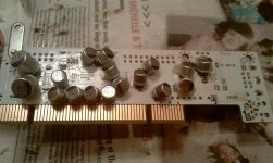
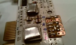
Iam using now only one SMD ALU cap and one 18nF MKP so they fit in boardI'd appreciate a photo showing cap package/fit
A couple of additional thoughts on the TPS regulator & bypass caps...
I did some experimenting about a year ago with additional local filter caps on the power supply pins of my computer music server's sound card, and ESI Juli@, digital portion only.
I originally did 100uf MLCC (TDKs) everywhere (about 20 total) at each chip's power pins (an relatively easy mod since they already had small C0G's on the back of the board at each location). This made a significant difference in clarity, bass impact, and dynamics AND took about 3 weeks before the ceramic cap signature diminished (a bit of harshness and emphasis in the trebles and over-emphasis of the bass). But the 'ceramic cap' sound never went away.
So I next tried replacing most of the 100uf MLCCs with 50uf or so Oscons. The ones that weren't Oscons were Panasonic 1uf PPS caps, only at the I2S/SPDIF generator chip (AK4114).
This version kept the clarity, but lost some of the bass and dynamics impact. OTOH, the trebles were VERY sweet on this version. These took about a week to settle in and stop changing.
Along with the local reservour caps, I'd also played with replacing the regulators which were modified Dexa units for the 3.3v & 5v. They got a different error op amp (OPA827's) and some additional power bypassing at the op amp pins. With the Oscon trial, I also swapped out 10uf MLCCs there for an Oscon/1uf PPS combon on the 5v reg and 2 1uf PPS on the 3.3v reg where I had less room.
It seemed I needed to be somewhere between the two trials, so the next try used the 100uf MLCCs at each of the deep digital chips (PCI Audio Controller, processor, memory, etc) and kept the PPS at the I2S/SPDIF output chip, the Oscon/PPS combo at the regulator error amps, and added some 1uf PPS caps at the reg's output on the boards.
This was the best of the trials and I've lived with that since. Again, it took a good 3 weeks of constant on and playing to do away with the ceramic cap signature.
I do want to try an all PPS version, but soldering in the 1uf PPS caps across the existing C0G caps without damaging the PPS caps would be very challenging (the whole mod is very challenging!) and I suspect that reducing the amount of capacitance by that much at the power inputs to the deep digital chips would not be an improvement.
All of this is to say these things:
1. In my experience using MLCCs in a digital circuit, it takes a good 3 weeks for the sound to settle.
2. If you try the MLCCs again and don't like them after they settle-in, try PPS caps as someone else suggested, perhaps as bypasses across mid-sized Oscons (10uf-50uf or so). I use either through-hole or SMD (with the plastic base removed) Oscons and bend the pins so I can nestle the PPS caps at the base of the Oscons soldered between the two pins, with them bent to allow soldering to the pads while keeping the leads ultra-short. I use a dab of hot-melt glue to help keep things from moving and damaging the PPS caps during mounting and mounting to the board.
3. Funny that Bunpei hasn't mentioned this, but I know that one of the updates to their SD card player is to add some PPS caps as bypasses at the chips.
4. That seems to be getting more popular, with John Brown in the monster TDA1541 thread doing that along with EUVL in the latest version of his ES9022 DAC card (check the latest pix he posted of them... also, I'm using that card mounted on the Juli@) and Fitzfish using them on his ES9022 (or ES9023, I don't remember)-based DAC.
Greg in Mississippi
P.S. Bunpei, do you still use the large CDE Polyprop caps on your DAC's AVCC?
Attachments
Last edited:
"a bit of harshness and emphasis in the trebles and over-emphasis of the bass"... this is not far from how I would describe what happened when changing the 6 V feed to the Fifo/clock from LT1963 to one of Ians TPS7A4700 boards. This on a single clock 11,28 board. But I understand I have to wait 3 weeks now ...
...Are you using the MCU on board TPA Buffalo III SE? How is your power on sequence? Before you turn power of BIIISE on, your synchronous master clock must be supplied to the ES9018 device so that the chip can receive initial register setting commands sent from MCU via internal I2C bus. Otherwise, ES9018 starts with its hardware defaults that lack input redirections.
In the case of Buffalo III, any manual DIP switch change triggered a whole register setting again and that enabled a normal operation.
on board MCU (cchd950 100MHz) is present (not unsoldered) XO_vdd trident module is off so the cchd is not powered in "my" synchro mode . clock signal from Ian`s XO module sending by u.fl cable to u.fl socket on TPA BIIISE board.
Hmm... it could be power up sequence problem - my power supply for FIFO is slightly slower (it is delta11 from amb ) than BIIIse PS ( Placid HD) .... I`ll try to swap it ... thanks Bunpei !
Hi Greg,
I had similar impressions on sound characteristics of those type of caps as you described. It's interesting.
As I did not use San-Ring (a name of Japanese small manufacturer) Copper foil PPS film capacitor on the TPS7A4700 evaluation board this time, I did not write about it.
Bunpei
P.S. I will report the use of CDE giant film capacitors on SDTrans thread because I am afraid that it is off topic here.
I completely agree with your expression, "Everything matters!" based on my experiences.
Last I combined the default set of MLCC's, that is on Si board, with an alternative set of Ian's MLCC's. Despite the fact, that I did not like none of the sets used separately, used together gave very good result to me. Sound is natural with good timbre and quiet black background without any annoying artifacts. Ian can you tell what specific types of capacitors are using?
- Home
- Source & Line
- Digital Line Level
- Asynchronous I2S FIFO project, an ultimate weapon to fight the jitter