hi, a new one again. just wonder if any one done an i/v stage for this dac board: DAC AD1865, NOS 2.0 Balanced output?
there is very short thread feb2011, but not mush for me!
i put a pair of Sowter9545 with secondaries in series. without any i/v resistor it gives 1:10 ratio. when playing a -20db pink-noise i get 1.6v. did many tries whit different i/v resistor but the output decreased dramatically!problems;
1- it's too low for me. my PSAudio DL3 gives 2.8v out!
2- the sound is not so satisfyingly either!
3- no interests in tubs. found a JFET concept that seems good but difficult to place it after trannys! the resistors here and there are just killing!
4- any help?
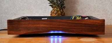
now through the beauty out of the window! almost!
there is very short thread feb2011, but not mush for me!
i put a pair of Sowter9545 with secondaries in series. without any i/v resistor it gives 1:10 ratio. when playing a -20db pink-noise i get 1.6v. did many tries whit different i/v resistor but the output decreased dramatically!problems;
1- it's too low for me. my PSAudio DL3 gives 2.8v out!
2- the sound is not so satisfyingly either!
3- no interests in tubs. found a JFET concept that seems good but difficult to place it after trannys! the resistors here and there are just killing!
4- any help?
now through the beauty out of the window! almost!
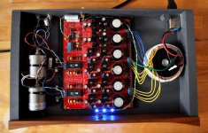
Attachments
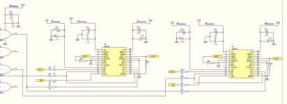
use good resistor like I/V (200ohm) and an active output stage like my schematic
Hi-Resolution System 192KHz 24bit with EMU 0404 USB
see hybrid design
Hi-Resolution System 192KHz 24bit with EMU 0404 USB
see hybrid design
Raindrop hui's IV stages are not too bad, he sells HDAM, FET, and Two tube versions.
I'm sure any of them would be very acceptable for use with this kit. Why not just ask him which works best and buy one of these?
Perhaps you should not rule out the tube output stages, as I have recently tried a tube output stage, and found that it is clearer, gives better front to back depth, less grain and sibilance than any op-amp output stage I have tried before. Depending upon the value of the cathode resistor bypass capacitor, you can get a sound that is "tubey" or sound that is crisp and clear, and you would never recognize that it is a tube, just clean sound. (my preference)
I have not tried a class A mosfet output stage, so perhaps these are also as good?
Last edited:
Hi,
First, I had a DAC using balanced AD1865 and the same Sowter transformers for direct out.
NDFG. The transformers seem unsuited. Sound sbad. The whole DAC sounded unoffensive, but zero dynamics, zero engagement, tiny soundstage.
Second, if you get 1.6V with -20dB pink noise, this is EXTREMELY HIGH LEVEL, eight times as much as would normal.
I would also expect the frequency response is not flat and the sound will be very distorted.
It should do that. It needs to do that. With the recommended I/V resistors, hookup etc and two DAC's output should be 2V from a 10K output Impedance, meaning the load must be greater than 100K and very short, very low capacitance connection cables MUST be used.
It may be better to leave the input load off and load the secondary with 10KOhm.
It gives 2.8V with -20dB noise?
Any help? The way you insist on approaching it, not really.
I would suggest to convert from balanced to parallel DAC's (this improves SNR by 3dB, instead of making it 3dB worse, as balanced does) and using a simple output stage, using either tubes or J-Fets as gainstage, unless you can get a good quality transformers. Even then you will need I/V resistors.
I think you need to think this through a little more overall.
Ciao T
i put a pair of Sowter9545 with secondaries in series. without any i/v resistor it gives 1:10 ratio. when playing a -20db pink-noise i get 1.6v.
First, I had a DAC using balanced AD1865 and the same Sowter transformers for direct out.
NDFG. The transformers seem unsuited. Sound sbad. The whole DAC sounded unoffensive, but zero dynamics, zero engagement, tiny soundstage.
Second, if you get 1.6V with -20dB pink noise, this is EXTREMELY HIGH LEVEL, eight times as much as would normal.
I would also expect the frequency response is not flat and the sound will be very distorted.
did many tries whit different i/v resistor but the output decreased dramatically!problems;
It should do that. It needs to do that. With the recommended I/V resistors, hookup etc and two DAC's output should be 2V from a 10K output Impedance, meaning the load must be greater than 100K and very short, very low capacitance connection cables MUST be used.
It may be better to leave the input load off and load the secondary with 10KOhm.
1- it's too low for me. my PSAudio DL3 gives 2.8v out!
It gives 2.8V with -20dB noise?
3- no interests in tubs.
found a JFET concept that seems good but difficult to place it after trannys!
the resistors here and there are just killing!
4- any help?
Any help? The way you insist on approaching it, not really.
I would suggest to convert from balanced to parallel DAC's (this improves SNR by 3dB, instead of making it 3dB worse, as balanced does) and using a simple output stage, using either tubes or J-Fets as gainstage, unless you can get a good quality transformers. Even then you will need I/V resistors.
I think you need to think this through a little more overall.
Ciao T
thanks so much Thorsten and others for the posts. i had given up the hope to get any answer from people.
tubs seemes very complex to me! high voltage aso! maybe in a near future!
i put together a simpler version of an i/v stage called JFET_Cdout with the 10k resistor it gives the famous 1.6 volt again!!! reducing the resistor hopefully gives more output. correct?
and finally, what your suggestion for the best sounding solution in this case?
best regards
yes it is so! 0.33v over the chip. through the secondaries with (1:10 ratio) it gives 1.6v! believe me! is something wrong?Second, if you get 1.6V with -20dB pink noise, this is EXTREMELY HIGH LEVEL, eight times as much as would normal.
done. 0.16v output. might be interesting to know 0.07v over the chip!It may be better to leave the input load off and load the secondary with 10KOhm.
yse. this dac gives 2.8v out according the spec. my measuring too! works perfect through stepped attenuator to the solid state power-amp!It gives 2.8V with -20dB noise?
this mod to the board is more than i can manage to do. i modified the digital input stage and some recapping according to some threads in DiyAudio.I would suggest to convert from balanced to parallel DAC's (this improves SNR by 3dB, instead of making it 3dB worse, as balanced does) and using a simple output stage, using either tubes or J-Fets as gainstage, unless you can get a good quality transformers. Even then you will need I/V resistors.
tubs seemes very complex to me! high voltage aso! maybe in a near future!
i put together a simpler version of an i/v stage called JFET_Cdout with the 10k resistor it gives the famous 1.6 volt again!!! reducing the resistor hopefully gives more output. correct?
and finally, what your suggestion for the best sounding solution in this case?
best regards
- Status
- This old topic is closed. If you want to reopen this topic, contact a moderator using the "Report Post" button.