Hello Dear Digital Line Lovers,
this little application written in Microsoft Visual Basic 2010 Express installs on any modern Windows PC. If like me you own an Intel DualCore T3000 laptop clocked at 1.8 GHz, you'll be amazed how today's computers do allow some brute force computing, and still a comfortable user interface without huge processing delays.
Yes indeed, this small application is simulating what's happening inside a processor having 16, 24 or 32 bits data words as storage combined to a 32, 48 or 64 bits multiplier-accumulator.
There is also the possibility to run the calculations using the maximum resolution the PC can deliver, using the native Double (Float) format of the Microsoft Visual Basic 2010 Express compiler.
This small application helps you calculating your IIR coefficients basing on an intuitive approach.
First of all, you need to provide the cutoff frequency (say 200 Hz) and the Q (say 0.707). This way the program is able to calculate the retroactive coefficients of the IIR (the resonating cell).
Then you need to specify how much highpass, bandpass and lowpass you want in the transfer function. You can combine the thee elements in any proportions. This enables you to generate all possible 2nd order transfer functions including pure phase shifters (allpass), notches, etc.
The five corresponding coefficients of the IIR get then listed.
Up to four 2nd order IIRs can be cascaded.
What you get as result is the Bode Plot of the IIR filter cascade. The Bode Plot gets calculated using what you may call the brute force again : a signal gets generated at the input (a white noise), a FFT is then calculated both on this signal and the signal coming out of the cascaded filters. A triangular window is used as default. The comparison between the input signal and the filtered signal gives the Bode Plot, in magnitude and in phase. You can decrease the level of the input signal. More about this below.
What you get also as result is the Spectrum Plot of the output of the filter cascade. In order to get something useful, the input signal is not anymore a white noise, but a sinus having the edges precisely matched to the sampling window. The frequency can thus be 1/256 of Fs, or 1/512 of Fs and so on. Using such trick, we meet the periodicity criterion and as a consequence the spectrum comes out without any sidebands or other transients effects. This feature enables a rectangular window to be used, and such rectangular window is used by default.
Here again you can decrease the level of the input signal. When decreasing the signal level to, say, -70 dB, and if using a 16 bit data and a 32 bit accumulator, you quickly realize how the dynamic range gets limited. The harmonics are quite present. Below a certain threshold the signal vanishes. Sometimes depending on the filters setting and input signal amplitude and shape, you may get a DC offset that mutates into a triangular wave (say at -60 dB), like the filter turned into a very low frequency oscillator.
You then realize that adding some dither may help preventing the filter getting crazy.
Fiddling with the parameters, you may discover that other configurations like the 24 bit storage and 48 bit accumulator are not completely free of artefacts of this sort when using 2nd order IIRs having a cutoff frequency below 60 Hz or so.
There is also an oscilloscope view. You can view the time evolution of the above signals. The oscilloscope view allows you to see the effects of the finite quantization at the very low levels like -90 dB or so.
An interesting case study is a very low frequency highpass filter, 2nd order, say 25 Hz, with a Q of 0.707 or so. You may need such highpass as infra-bass protection, and/or if you intend to build a digital Linkwitz transform filter, aka deep bass flattener. If you look to the IIR coefficients, you'll see how much it was needed to attenuate the input signal before it reaches the resonating cell. Indeed, the non-recursive (direct) coefficients (CDA, CDB, CDC) have very small values, less than 1/1000. Consequently, the accumulator gets as input 1/1000th or so of the original input data. Following this you get the huge gain buildup caused by the retroactive coefficients (CRA, CRB). The situation is not as bad as it may appear, thanks to the accumulator being far more precise than the data (48 bits instead of 24 bits), able to compute and retain 48 decimals. But unfortunately, as soon as the signal escapes the accumulator, all the tiny decimal bits get discarded. Only the 24 first decimals get stored, making the intermediate storages for the delay cells.
This means that when using a DSP56K architecture (24 bit storage and 48 bit accumulator), one should use an enhanced-precision arrangement when implementing 2nd order IIRs operating below 60 Hz or so. The storages should thus be wider than 24 bits, say 48 bits or so.
Some Analog Device chips are currently makteted as having 28 bit internal storages able to represent numbers between -7.999999 and +8 roughly. Like the DSP56K, they have a 56 bit accumulator. One way to use this 28 bit feature in IIRs is to consider that the Analog Device chips are able to represent numbers between -0.999999 and +1 roughly using 28 bits in the storage cells. Don't know yet if designers are considering it this way. Please tell me if I need to add a 28 bit storage width in my little application.
Substractive crossovers are completely exposed to arithmetic errors in the deep bass range, like when crossing-over at a low frequency like 120 Hz or so. If the lowpass section is producing arithmetic errors, the highpass section that gets computed from the difference between the lowpass and the input (phase compensated or simply delayed like in the Lipshitz-Vanderkooy arrangements), will produce noise and distorsion.
A simple microcontroller like the PIC32 seems to have a fast 32x32=64 bit fixed point multiplier-adder, an asset for digital audio. However, the PIC32 does't have the needed I2S port for interfacing audio DACs and ADCs.
The ARM Cortex M4 microcontrollers (Freescale Kinetis and NXP LPC43xx) are now also coming with a fast 32x32=64 bit fixed point multiplier-adder. Some chips are equipped with one I2S port, just enough to handle a stereo input/output.
PC mainboards equipped with an Intel Atom CPU may be real killers in DSP audio, especially when executing code manipulating audio samples as Double Floats. USB can be used as audio input/output. However, software complexity is high, especially if using dedicated software drivers and a standard operating system like Windows (licence ?) or Linux.
So, today the choice of a dedicated DSP chip like the Freescale DSP56K 24/48 bits chip or the Analog Device 28/56 bits chip is still the easiest way to go, not because or the performance, not because of the flexibility, but simply because such chips are always equipped with multiple I2S ports enabling a glueless connexion to multichannel audio DACs.
The day ARM Cortex M4 controllers will be equipped with multiple I2S ports, a multichannel TDM port, or a HD audio port, we'll need reconsider.
Enjoy !
Steph
Attachments
The day ARM Cortex M4 controllers will be equipped with multiple I2S ports, a multichannel TDM port, or a HD audio port, we'll need reconsider.
That day is fast upon us - LPC4300 has plenty (16 lines) of 'soft' serial ports which can be used for I2S. Not sure exactly when that part's coming out - can't be more than six months out. In the meantime people can play with the LPC1800 series which has a similar peripheral set except for the soft serial ports. LPC1830 has recently changed status from 'Development' to 'Qualification' on NXP's site.
Hi abraxalito, I have two questions for you.
1.
Are you using the HITEX LPC1800 evaluation board ?
LPC1800 Evaluation Board - Downloads
2.
Do you know any other LPC1800-based evaluation board, LPCXpresso or NXP-sticks ?
Embedded Artists > Products > LPCXpresso
3.
Is it feasible to synchronize the 3 or 4 SPI ports of a Microchip PIC32, using a GPIO pin for the Frame_Sync signal, and getting a pseudo I2S solution able to generate 6 or 8 audio channels ? Do you think the PIC32-based TRAXMOD trick is applicable ? What to do if needing a bidirectional I2S channel like 2 audio-in and 2 audio-out ? Back in 2009, zilym wrote on the TRAXMOD forum : The PIC32 reads the left/right word clock for initially synchronizing the slave mode SPI to the DAC, then it continuously stays synchronized through the use of the DAC generated bit clock. If the PIC32 were to fail at continuously outputting perfect I2S data, you'd certainly immediately notice the audio being terrible because the PIC32 SPI would no longer be outputting words synchronized to the DAC generated word clock. In the months of use I've put my prototype boards through, I'm only seeing that happen if I zap the board with static electricity, which can cause enough disturbance of the I2S signals for the DAC and PIC32 to lose sync. Resetting the PIC32 to run through the left/right word clock initialization routine brings it back into working order. The 11.2896MHz master clock used by the DAC is also input to the processor on TRAXMOD-PIC32. This allows -everything- to be capable of running synchronously with audio. Internally, firmware has the option to run off of the 11.2896MHz clock directly (used initially by the left/right word clock synchronization routine), run faster through PLL multiplication of the 11.2896MHz clock (full power audio processing mode), or switch to an internal 7.37MHz FRC clock source (used when the audio buffers are full and the processor core is shutdown for extreme low power operation). Audio always continuously plays via DMA and slave mode SPI that is clocked by the DAC's bit clock, regardless of what clock source the processor core is using.
Re: Project evolution for Audiophile ?
Best regards
Steph
Are you using the HITEX LPC1800 evaluation board ?
No, not yet working on that part - the 17XX and 18XX are still a bit advanced for me as I only got into ARM from scratch this spring. So my parts of interest at present are LPC11XX and LPC13XX. The boards I'm using for these are ultra-cheap ones from Taobao. I can provide links if you're interested.
Do you know any other LPC1800-based evaluation board, LPCXpresso or NXP-sticks ?
No I wasn't even aware that eval boards were generally available on that part yet. Imagined that existing customers must have been sampled as on YouTube I've seen eval boards for the LPC43XX and the 18XX is a little ahead in the development cycle as I understand it.
Is it feasible to synchronize the 3 or 4 SPI ports of a Microchip PIC32, using a GPIO pin for the Frame_Sync signal, and getting a pseudo I2S solution able to generate 6 or 8 audio channels ?
As I'm 100% focussed on ARM these days I've barely given a squint in the direction of Microchip, so can't help you on this one.
I can say though that on the parts I'm using (which are seriously cheap and also lower power than PIC32) although they don't have a dedicated I2S port its not a very difficult matter to re-purpose the SSP to do this function. Just requires a little dedicated study of the datasheet (and in my case, an email question to ARM too).
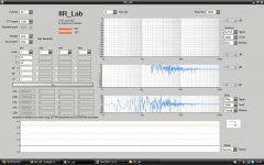
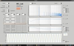
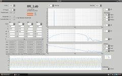
Here is the Linkwitz transform example (aka deep bass flattener). See the attached .jpg files.
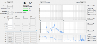
16-bit storage & 32-bit acc arrangement
Note the many harmonics when inputting the -20 dB signal.
Note how the output signal vanishes when inputting the at -40dB signal. Massive DC buildup is taking place here with a -0.15 Volt DC output referred to 1.00 Volt full scale. Viewing the same output using a much longer timebase may show that we get a very low frequency oscillation at such high amplitude.
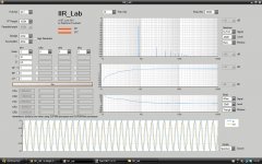
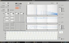
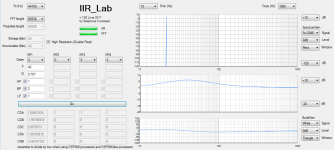
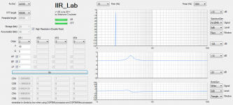
24-bit storage & 48-bit acc arrangement
Note the presence of some artefacts. They however remain below -100dB.
Note how bumpy the transfer function (Bode plot) becomes when inputting the -40dB signal. Compare with the transfer function when inputting the -20dB signal.
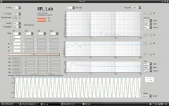
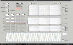
32-bit storage & 64-bit acc arrangement
Note how clean the output is. The output remains nice and clean even when inputting the -40 dB signal. The transfer function (Bode plot) remains consistent.
Cheers,
Steph
16-bit storage & 32-bit acc arrangement
Note the many harmonics when inputting the -20 dB signal.
Note how the output signal vanishes when inputting the at -40dB signal. Massive DC buildup is taking place here with a -0.15 Volt DC output referred to 1.00 Volt full scale. Viewing the same output using a much longer timebase may show that we get a very low frequency oscillation at such high amplitude.
24-bit storage & 48-bit acc arrangement
Note the presence of some artefacts. They however remain below -100dB.
Note how bumpy the transfer function (Bode plot) becomes when inputting the -40dB signal. Compare with the transfer function when inputting the -20dB signal.
32-bit storage & 64-bit acc arrangement
Note how clean the output is. The output remains nice and clean even when inputting the -40 dB signal. The transfer function (Bode plot) remains consistent.
Cheers,
Steph
Attachments
-
 Linkwitz transform 16-bit storage & 32-bit acc (-20 dB in).jpg272.4 KB · Views: 451
 -
 Linkwitz transform 16-bit storage & 32-bit acc (-40 dB in).jpg243.2 KB · Views: 421
 -
 Linkwitz transform 24-bit storage & 48-bit acc (-20 dB in).jpg269.8 KB · Views: 408
 -
 Linkwitz transform 24-bit storage & 48-bit acc (-40 dB in).jpg269.7 KB · Views: 393
 -
 Linkwitz transform 32-bit storage & 64-bit acc (-20 dB in).jpg268.7 KB · Views: 79
 -
 Linkwitz transform 32-bit storage & 64-bit acc (-40 dB in).jpg268.9 KB · Views: 80
Last edited:
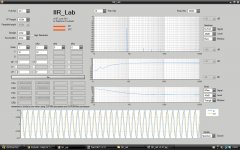
Here is the 2nd order Bessel highpass example (aka deep bass protector). See the attached .jpg files.
16-bit storage & 32-bit acc arrangement
Note how the output signal vanishes when inputting the -20 dB signal and the -40dB signal. Massive DC buildup taking place. Viewing the same output using a much longer timebase may show that we get a very low frequency oscillation at such high amplitude.
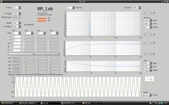
24-bit storage & 48-bit acc arrangement
Note the presence of some artefacts. They however remain below -100dB.
Note how bumpy the transfer function (Bode plot) becomes when inputting the -40dB signal. Compare with the transfer function when inputting the -20dB signal.
32-bit storage & 64-bit acc arrangement
Note how clean the output is. The output remains nice and clean even when inputting the -40 dB signal. The transfer function (Bode plot) remains consistent.
Cheers,
Steph
16-bit storage & 32-bit acc arrangement
Note how the output signal vanishes when inputting the -20 dB signal and the -40dB signal. Massive DC buildup taking place. Viewing the same output using a much longer timebase may show that we get a very low frequency oscillation at such high amplitude.
24-bit storage & 48-bit acc arrangement
Note the presence of some artefacts. They however remain below -100dB.
Note how bumpy the transfer function (Bode plot) becomes when inputting the -40dB signal. Compare with the transfer function when inputting the -20dB signal.
32-bit storage & 64-bit acc arrangement
Note how clean the output is. The output remains nice and clean even when inputting the -40 dB signal. The transfer function (Bode plot) remains consistent.
Cheers,
Steph
Attachments
-
 Bessel 32Hz Highpass 16-bit storage & 32-bit acc (-20 dB in).jpg265.2 KB · Views: 82
 -
 Bessel 32Hz Highpass 16-bit storage & 32-bit acc (-40 dB in).jpg241.1 KB · Views: 67
 -
 Bessel 32Hz Highpass 24-bit storage & 48-bit acc (-20 dB in).jpg270 KB · Views: 57
 -
 Bessel 32Hz Highpass 24-bit storage & 48-bit acc (-40 dB in).jpg271 KB · Views: 45
 -
 Bessel 32Hz Highpass 32-bit storage & 64-bit acc (-20 dB in).jpg269.5 KB · Views: 47
 -
 Bessel 32Hz Highpass 32-bit storage & 64-bit acc (-40 dB in).jpg268.6 KB · Views: 43
Is it smarter to use two cascaded 1st order highpass as deep bass protector, instead of one 2nd order Bessel highpass ?
Yes indeed. Even the 16-bit storage & 32-bit accumulator combination get a new life using this approach. And the 16-bit storage & 32-bit accumulator combination is delivering near-perfect results. See the attached .jpg files.
Cheers,
Steph
Yes indeed. Even the 16-bit storage & 32-bit accumulator combination get a new life using this approach. And the 16-bit storage & 32-bit accumulator combination is delivering near-perfect results. See the attached .jpg files.
Cheers,
Steph
Attachments
-
 Two cascaded 1st order 32Hz Highpass 16-bit storage & 32-bit acc (-20 dB in).jpg273.5 KB · Views: 57
 -
 Two cascaded 1st order 32Hz Highpass 16-bit storage & 32-bit acc (-40 dB in).jpg275.7 KB · Views: 55
 -
 Two cascaded 1st order 32Hz Highpass 24-bit storage & 48-bit acc (-20 dB in).jpg271.7 KB · Views: 51
 -
 Two cascaded 1st order 32Hz Highpass 24-bit storage & 48-bit acc (-40 dB in).jpg270.9 KB · Views: 56
Here, a few design ideas using a 8th-order Bose 3-chamber subwoofer.
Note how DSP enables tracking the subwoofer phase response.
We get an all pass filter having the same phase and module response as the subwoofer, between 50 Hz and 1000 Hz. This may be used in a substractive crossover like the Lipshitz-Vanderkooy phase-compensated. Kind of generalized Linkwitz-Riley.
We also can get a lowpass filter having the same phase and module response as the subwoofer, between 50 Hz and 1000 Hz. This may be used in a substractive crossover like the Lipshitz-Vanderkooy propagation delay-compensated. The big advantage is the accurate global phase. If you put a squarewave in, you get a squarewave out. Is this commercially available ?
Cheers,
Steph
Attachments
-
 8th-order 3-chamber Bose subwoofer (digital model).jpg275.1 KB · Views: 60
 -
 8th-order 3-chamber Bose subwoofer (digital model - low pass section only).jpg271.2 KB · Views: 56
 -
 8th-order 3-chamber Bose subwoofer (digital model - low pass section only) (24-bit storage & 48-.jpg271.6 KB · Views: 52
 -
 8th-order 3-chamber Bose subwoofer (digital model - all pass version).jpg269.1 KB · Views: 52
Last edited:
Hi abraxalito,
currently my audio DSP application would require 1 SPI as input (reading a stereo ADC) and 2 SPI as output (writing three stereo DACs). Plus one SPI for controlling the ADCs and DACs volumes and modes.
Do you think there is a cheap ARM able to provide this like having four SSPs, one used as SPI plus three used as I2S ?
I intend using a Freescale DSP56374 (and possibly the upcoming Elektor audio DSP board), but the ARM would have an advantage if equipped with a 32 bit storage and (possibly ?) a 64 bit MACC.
What do you advise ?
Steph
Hi steph,
I'd need to know a bit more about what you're doing with the DSP in order to make a sensible suggestion for you. PM me if you don't want to talk about such details in public. One of the main reasons I'm so enthusiastic about ARM for DSP is the low power - this directly translates to low noise. The Freescale parts are extremely capable but the power supply requirements and the clock speeds make low noise design much more problematic. The cheap ARMs I've been using don't have 64bit MACC, in fact the M0 does not even have a MAC instruction. However it does have single cycle 32*32 multiply which I use to good advantage in my FIR filter software. The prices and power draw are so low that it could even be economical to consider splitting the processing over 2 or 3 parts to get the interfaces you require.
I'd need to know a bit more about what you're doing with the DSP in order to make a sensible suggestion for you. PM me if you don't want to talk about such details in public. One of the main reasons I'm so enthusiastic about ARM for DSP is the low power - this directly translates to low noise. The Freescale parts are extremely capable but the power supply requirements and the clock speeds make low noise design much more problematic. The cheap ARMs I've been using don't have 64bit MACC, in fact the M0 does not even have a MAC instruction. However it does have single cycle 32*32 multiply which I use to good advantage in my FIR filter software. The prices and power draw are so low that it could even be economical to consider splitting the processing over 2 or 3 parts to get the interfaces you require.
Hi abraxalito,
what I intend to experiment is a so-called smart crossover enabling all sorts of topologies like the Bessel, Butterworth, Linkwitz-Riley, Lipshitz-Vanderkooy substractive phase-compensated and the the Liphsitz-Vandekooy substractive delay-compensated. Up to 3-way. In stereo.
Plus a Linkwitz transform (aka deep bass flattener) on all outputs for partially compensating the natural speaker highpass roll off.
Plus a global tone control using a few 1st order shelving filters and a few 2nd order bandpass equalizers.
Plus a protection against very low frequencies in the form of a highpass filter at the input.
Plus a short delay on every output for compensating any speaker time misalignment.
It looks quite complicated at first glance but in reality there are only a few routing switches. I'll draw a block diagram if you are interested.
The idea of using multiple ARM chips equipped with a single I2S, all hooked on a common stereo ADC, is a good idea.
Unfortunately, this may prove unpractical when considering substractive crossover arrangements where one ARM needs to output the lowpass signal to a DAC, while it also needs to send some intermediate digital audio to another ARM. I'll take some time thinking about this.
Yes indeed, the Cortex M0 are good candidates also, even if they are not equipped with an accumulator. The big advantage is in their 32x32=64 bit multiplication.
The Cortex M4 should be a massive hit, like the Freescale Kinetis and NXP LPC43xx. They run at more than 100 MHz and they have a fast 32x32=64 MACC instruction.
Like you I am very positive about ARM in DSP audio, and I will be even more positive after finding inexpensive ARM chips equipped with 4 serial synchronous interfaces, three should be able to emulate three I2S ports with one common Frame_Sync pin, and one should be able to SPI-control the volumes and the codec modes.
Or maybe, finding inexpensive ARM chips equipped with one TDM serial port, which is the multichannel version of I2S. Usually, one TDM serial port can handle up to 8 audio channels as outputs.
Or maybe, finding inexpensive ARM chips equipped with a HD audio port, which is a special version of TDM, also able to handle up to 8 audio channels as outputs.
What development tool are you using for ARM ? Is it affordable ? Are there decent debug possibilities, well suited to realtime processing ?
Steph
Hello Steph
I read the first part of the thread , your program creates the IIR coefficients for the filter your are going to generate.
I would like to build the hardware of what you are preposing, just a thought have you thought of using the Sabre dac ES9018 it gives 8 high performance DAC outputs. The input ADC could be the ES90102A which is high performance also .
Regards
Arthur
I would say any hardware you dare submitting me. A nice proposition would be the Elektor DSP56374 board, once fitted with multiple DACs at the output. Another nice proposition would be a x86 PC running Windows, using the built-in Realtek 6 channel HDaudio subsystem or a USB2 Terratec DMX 6Fire multichannel audio card.What hardware do you need for this to be played with ?
Steph, can you explain a bit more as to how the HP, BP, and LP quantities are blended? I do quite a bit with peaking EQ patches and, while HP = 1, 0.1 < BP < 10, LP = 1, produces peaking EQ I'm seeing more signs of numerical issues for filters centered at low normalized frequencies than I'd expect for double precision floats. It's probable this is just the relatively limited FFT length and window selection---any chance of a drop with 256k+ points and a Hanning or Kaiser window?Then you need to specify how much highpass, bandpass and lowpass you want in the transfer function.
Regardless, thanks for putting this together. Handy tool for estimating various fixed point configurations against doubles. I ran a few cases with the biquad cascades I tend to use and found the noise floor on 32 bit storage with 32 bit accumulation is consistently -140dB or better. I'm not aware of any DACs which can compete with this, though there are a couple op amps that come close.
")
FWIW, install of 1.0.0.23 went smoothly on my Win7 laptop with non-admin login; prompts for elevation at all the right places. It did spend a while doing something with .NET 4 client profile install even though full .NET 4 was already installed---I think the the detection of the existing install was probably just slow. A small feature suggestion if you happen to revisit this: a vertical scroll bar for the UI and better detection of the task bar would be nice. My screen's 768 pixels high so the bottom of the graph gets chopped off after resizing IIR Lab's window so its lower portion isn't hidden behind the task bar.
I ran a few cases with the biquad cascades I tend to use and found the noise floor on 32 bit storage with 32 bit accumulation is consistently -140dB or better. I'm not aware of any DACs which can compete with this, though there are a couple op amps that come close.
How do you go about measuring the noise floor? Estimate it from an FFT or some other method?
Yep, FFT estimate. IIR Lab displays the floor in its upper right graph, though most numerical configurations require selecting a lower bound smaller than the default of -120dB to see it. Provided you choose one of the Fs/2^n stimulus frequencies to get round the window, anyway---with other frequencies you'll just get the window's sideband level (unless the arithmetic's truly atrocious).
The blend occurs thanks to the non-recursive coefficients. In IIR_Lab, define four IIRs (IIR1, IIR2, IIR3, IIR4) having the same F and Q. Play with their HP, BP, LP factors and observe how the CDA, CDB and CDC coefficients get modified. Observe how the CRA and CRB coefficients remain the same. In IIR_Lab, the four IIRs get connected in series. Your PEQ (parametric equalizer) is thus a series one, not a "parallel" one that you may find in "graphic" equalizers, those last ones needing to fiddle with Q.Steph, can you explain a bit more as to how the HP, BP, and LP quantities are blended? I do quite a bit with peaking EQ patches and, while HP = 1, 0.1 < BP < 10, LP = 1, produces peaking EQ I'm seeing more signs of numerical issues for filters centered at low normalized frequencies than I'd expect for double precision floats. It's probable this is just the relatively limited FFT length and window selection---any chance of a drop with 256k+ points and a Hanning or Kaiser window?
I tried to reproduce your low frequency PEQ at 30 Hz Q=0.707 with HP = 1, 0.1 < BP < 10, LP = 1. On my side, the SpectrumGen plot doesn't exhibit distorsion using the High Resolution (Double Float). FFT size 65536 and test signal Fs/2048. SpectrumPlot from 10 Hz to 1000 Hz, Rect. Window. The corresponding BodeGen is clean (+20db to -20dB), Triangle Window, which means that the 65536 FFT size remains adequate. If you switch to 24 bit storage and 56 bit Acc, you get a -90 dB H2 distorsion, -98dB H3 distorsion on a 0dB signal. This being said, I agree that for the BodeGen plot, using a more elaborate window like Hanning or Kaiser could deliver cleaner plots, minimizing the disturbance caused by the non-periodic nature of the test signal, which is a white noise in case of the BodeGen plot.
I just did an install on a fresh computer, a HP DM1-4033SF having a 1366x768 screen, running Windows 7. Like you wrote, the install automatically triggered a fresh .net client download, quite annoying. Like you wrote, there was a security warning asking for the IIR_Lab install confirmation. Regarding the screen size, I wrote IIR_Lab on a WinXP laptop equipped with a 1280x800 screen. Next time I modify IIR_Lab, I'll remember to fit it on a Win 7 computer hooked on a 1366x768 screen, and possibly also a 1280x720 screen using scroll bars.FWIW, install of 1.0.0.23 went smoothly on my Win7 laptop with non-admin login; prompts for elevation at all the right places. It did spend a while doing something with .NET 4 client profile install even though full .NET 4 was already installed---I think the the detection of the existing install was probably just slow. A small feature suggestion if you happen to revisit this: a vertical scroll bar for the UI and better detection of the task bar would be nice. My screen's 768 pixels high so the bottom of the graph gets chopped off after resizing IIR Lab's window so its lower portion isn't hidden behind the task bar.
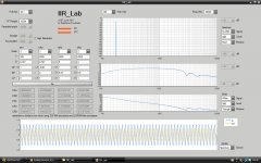
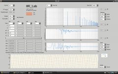
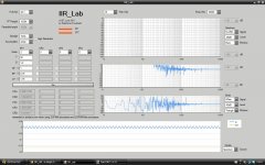
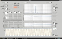
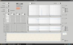
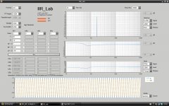
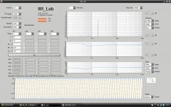
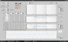
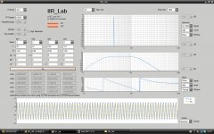
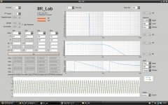
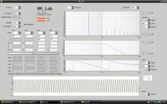
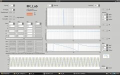
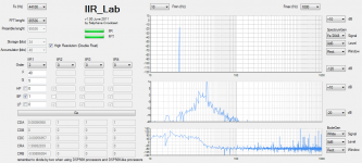
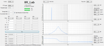
Hmm, wiggles should be visible at Q = sqrt(2)/2. They get worse at higher Q. Attaching a few screen grabs from IIR lab on my side. I also found if I uncheck the BP box I get an even more ragged notch filter. And if I uncheck HP and LP in the Q = 5 example I get a different BP response each time I hit the go button. Having looked at this more I am thinking perhaps the white Bode gen option is actually random rather than using a delta function and the result is errors in the Bode display due to the noise not averaging to zero at low normalized frequencies.
From what I can tell at a glance the filters seem to be direct form 1 and I get that the blending is controlled by the numerator coefficients since the denominator's the same for HP, BP, and LP biquads. The BP looks like the 0dB peak gain form and the weighting of each form by the HP, BP, or LP coefficient entered in the UI is clear. What's not clear to me is how the numerator coefficients are calculated. I can certainly try to reverse engineer the calculation method from watching the coefficents but was thinking it might be simpler just to ask.
From what I can tell at a glance the filters seem to be direct form 1 and I get that the blending is controlled by the numerator coefficients since the denominator's the same for HP, BP, and LP biquads. The BP looks like the 0dB peak gain form and the weighting of each form by the HP, BP, or LP coefficient entered in the UI is clear. What's not clear to me is how the numerator coefficients are calculated. I can certainly try to reverse engineer the calculation method from watching the coefficents but was thinking it might be simpler just to ask.
Cool, thanks. Wouldn't hurt to tidy up the tab ordering of the controls too.Next time I modify IIR_Lab, I'll remember to fit it on a Win 7 computer hooked on a 1366x768 screen, and possibly also a 1280x720 screen using scroll bars.
Attachments
- Status
- This old topic is closed. If you want to reopen this topic, contact a moderator using the "Report Post" button.
- Home
- Source & Line
- Digital Line Level
- IIR_Lab : a design help for digital audio filters