how to mod the DCX
AK4393 datasheet, Pinout ,application circuits Advanced Multi-Bit 96kHz 24-Bit ?? DAC
The DAC has differential outputs for each channel, in addition to signal ground. You will be using the differential outputs ONLY and NOT the signal ground.
A quick how-to:
1) Probably the easiest (and safest) is to use an ohmmeter to track the Aout Left(- & +, pins 20,21) and Aout Right (-&+, pins 22, 23) signal leads from each of the 3 DACs to the pins that extrude from the bottom of the board where they connect to the ribbon cable, solder flying leads to those pins only, and then snip ONLY the 4 corresponding leads on the ribbon.
Caution! It is very risky to try and lift the smd leads and solder directly to the DAC. That operation is pointless when you have ready made connection points poking out prominently under the board! No need to cut traces on the board, snip 'em on the ribbon, or make up a new ribbon with those 4 lines missing.
This will leave you with a fully functional unit. Please note the DCX has a digital input which connects through the I/O board in back, and removing the ribbons that connect to that board will ALSO remove your digital input! My advice is to leave well enough alone and mod only the DAC outputs.
When tracing with the ohmmeter, the proper connection point for each signal line will read close to Zero ohms, other points will show impedances of several thousands of ohms or higher. Please note that a signal continuity meter will give you many "false" points by showing "connection" across many points, so rely ONLY on the ohm-meter readings!
2) You will need to put coupling capacitors on EACH of the flying leads as EACH of the signal lines has +2.5Vdc offset.
I would recommend a very good cap like the Mundorf Zn in 2.2 or 3,3uF value. But that gets expensive. Or you can do as Sendler does on his mods and use 5 of the Dayton 0.47uF in parallel for a total of 2.35uF, as those are less expensive and still very good quality.
3) Snip all 3 pins of the output xlr 's connectors at the base of the I/O board, and get them ready for connection to the coupling caps. (I don't feel it is necessary to use the resistors that Jan Didden uses. Others might disagree.) This will disconnect the output op-amps completely from the signal, although they are still connected to the power supplies. Just leave 'em alone.
4) When connecting to the xlr's you might want to follow the accepted convention and use pins 2 and 3 for the signal pins. Use pin 2 for positive signal, pin 3 for negative signal and leave pin 1 (ground) disconnected. That way, if you ever decide to use a decoupling transformer for galvanic isolation, you can use off the shelf items without needing to rewire the connections.
5) You will need to make an adapter for xlr to RCA, connect pin 2 to the RCA + (the inside pin) and connect pin to the rca return line (the outer connector).
That should work. Good luck!
Find the AKM 4393 pinout diagram atAt this point I'm into keeping it as simple as possible. I would like to try just bypassing all the output junk and just go straight from the DAC to RCA single ended.
So it looks like the very simplest is to somehow disconnect the output from the DAC to the rest of the stuff and connect it to a coupling cap. Use the sig gnd on the XLR output connectors as the new RCA sig gnd.
This all brings up a few questions:
1. What's the best way to get to the DAC output?
A. Cut the ribbon cable and tack onto the ends that go to the DAC?
B. Make and install a new ribbon cable?
1) Does this eliminate some functions of the DCX that are needed?
C. Cut the output leads on the DAC chip and fold them up. Then solder the new output wires to them?
2. Do we need any kind of output filtering?
3. What values for the output caps? In my case I will probably be feeding amps with 50k input impedance.
AK4393 datasheet, Pinout ,application circuits Advanced Multi-Bit 96kHz 24-Bit ?? DAC
The DAC has differential outputs for each channel, in addition to signal ground. You will be using the differential outputs ONLY and NOT the signal ground.
A quick how-to:
1) Probably the easiest (and safest) is to use an ohmmeter to track the Aout Left(- & +, pins 20,21) and Aout Right (-&+, pins 22, 23) signal leads from each of the 3 DACs to the pins that extrude from the bottom of the board where they connect to the ribbon cable, solder flying leads to those pins only, and then snip ONLY the 4 corresponding leads on the ribbon.
Caution! It is very risky to try and lift the smd leads and solder directly to the DAC. That operation is pointless when you have ready made connection points poking out prominently under the board! No need to cut traces on the board, snip 'em on the ribbon, or make up a new ribbon with those 4 lines missing.
This will leave you with a fully functional unit. Please note the DCX has a digital input which connects through the I/O board in back, and removing the ribbons that connect to that board will ALSO remove your digital input! My advice is to leave well enough alone and mod only the DAC outputs.
When tracing with the ohmmeter, the proper connection point for each signal line will read close to Zero ohms, other points will show impedances of several thousands of ohms or higher. Please note that a signal continuity meter will give you many "false" points by showing "connection" across many points, so rely ONLY on the ohm-meter readings!
2) You will need to put coupling capacitors on EACH of the flying leads as EACH of the signal lines has +2.5Vdc offset.
I would recommend a very good cap like the Mundorf Zn in 2.2 or 3,3uF value. But that gets expensive. Or you can do as Sendler does on his mods and use 5 of the Dayton 0.47uF in parallel for a total of 2.35uF, as those are less expensive and still very good quality.
3) Snip all 3 pins of the output xlr 's connectors at the base of the I/O board, and get them ready for connection to the coupling caps. (I don't feel it is necessary to use the resistors that Jan Didden uses. Others might disagree.) This will disconnect the output op-amps completely from the signal, although they are still connected to the power supplies. Just leave 'em alone.
4) When connecting to the xlr's you might want to follow the accepted convention and use pins 2 and 3 for the signal pins. Use pin 2 for positive signal, pin 3 for negative signal and leave pin 1 (ground) disconnected. That way, if you ever decide to use a decoupling transformer for galvanic isolation, you can use off the shelf items without needing to rewire the connections.
5) You will need to make an adapter for xlr to RCA, connect pin 2 to the RCA + (the inside pin) and connect pin to the rca return line (the outer connector).
That should work. Good luck!
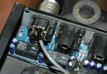
Or the opposite :If you are sure to never use the analog input A & B (but you can keep C), you can by-pass all the stuff with a cable going directly to the input SPDIF transformer. Here the XLR is upside down and traces cut.Please note the DCX has a digital input which connects through the I/O board in back, and removing the ribbons that connect to that board will ALSO remove your digital input! My advice is to leave well enough alone and mod only the DAC outputs.
Attachments
Find the AKM 4393 pinout diagram at
AK4393 datasheet, Pinout ,application circuits Advanced Multi-Bit 96kHz 24-Bit ?? DAC
The DAC has differential outputs for each channel, in addition to signal ground. You will be using the differential outputs ONLY and NOT the signal ground.
A quick how-to:
1) Probably the easiest (and safest) is to use an ohmmeter to track the Aout Left(- & +, pins 20,21) and Aout Right (-&+, pins 22, 23) signal leads from each of the 3 DACs to the pins that extrude from the bottom of the board where they connect to the ribbon cable, solder flying leads to those pins only, and then snip ONLY the 4 corresponding leads on the ribbon.
Caution! It is very risky to try and lift the smd leads and solder directly to the DAC. That operation is pointless when you have ready made connection points poking out prominently under the board! No need to cut traces on the board, snip 'em on the ribbon, or make up a new ribbon with those 4 lines missing.
This will leave you with a fully functional unit. Please note the DCX has a digital input which connects through the I/O board in back, and removing the ribbons that connect to that board will ALSO remove your digital input! My advice is to leave well enough alone and mod only the DAC outputs.
When tracing with the ohmmeter, the proper connection point for each signal line will read close to Zero ohms, other points will show impedances of several thousands of ohms or higher. Please note that a signal continuity meter will give you many "false" points by showing "connection" across many points, so rely ONLY on the ohm-meter readings!
2) You will need to put coupling capacitors on EACH of the flying leads as EACH of the signal lines has +2.5Vdc offset.
I would recommend a very good cap like the Mundorf Zn in 2.2 or 3,3uF value. But that gets expensive. Or you can do as Sendler does on his mods and use 5 of the Dayton 0.47uF in parallel for a total of 2.35uF, as those are less expensive and still very good quality.
3) Snip all 3 pins of the output xlr 's connectors at the base of the I/O board, and get them ready for connection to the coupling caps. (I don't feel it is necessary to use the resistors that Jan Didden uses. Others might disagree.) This will disconnect the output op-amps completely from the signal, although they are still connected to the power supplies. Just leave 'em alone.
4) When connecting to the xlr's you might want to follow the accepted convention and use pins 2 and 3 for the signal pins. Use pin 2 for positive signal, pin 3 for negative signal and leave pin 1 (ground) disconnected. That way, if you ever decide to use a decoupling transformer for galvanic isolation, you can use off the shelf items without needing to rewire the connections.
5) You will need to make an adapter for xlr to RCA, connect pin 2 to the RCA + (the inside pin) and connect pin to the rca return line (the outer connector).
That should work. Good luck!
Hi Jack,
Thanks very much for the very detailed instructions - they are great!
As you may recall I have been trying to decide between modding my DCX or getting two MiniDSP 2x8s. I have been waiting awhile hoping that some helpful SQ reports would come out on the relatively new 2x8. Unfortunately there has been very little reporting.
There were some earlier reports - I believe from some Aussies - that compared a heavily modded DCX to a regular MiniDSP (24/48). I think they preferred the SQ of the MiniDSP, but this is not a lot to base a decision on.
Since it's really time to get this project underway, here's what I'm now thinking:
1. My system is a left, center, right and sub. The L, R & C will be 2 way, but I want the electronics to be able to handle 3 way if I should make future changes. So this will require 4 inputs and 10 outputs (for 3 way). This is more than a single DCX or MiniDSP 2x8 can handle.
2. Mod the DCX per your instructions Jack.
3. Buy a MiniDSP 2x8.
I will then have all the I/O I need. I will also be able to do some real comparisons between the two devices. Whichever has the best SQ I will use on the L & R which are used for 2 channel listening. I can then use the remaining I/O for Center & sub.
I had been kind of leaning towards selling my DCX and gettting two MiniDSP 2x8s. But then I may never know which is the better one.
Thanks again Jack for spending all the time explaining your mod. And hopefully it will also benefit others.
Rod
Or the opposite :If you are sure to never use the analog input A & B (but you can keep C), you can by-pass all the stuff with a cable going directly to the input SPDIF transformer. Here the XLR is upside down and traces cut.
Thanks for the tip. I may want to use all three analog inputs so will have to keep that part stock.
Rod
- Status
- This old topic is closed. If you want to reopen this topic, contact a moderator using the "Report Post" button.