Hello All,
I have just bought a Musical Fidelity Digilog Dac which I intend to modify. I need some help as there is a previous repair which is not as good as I would like.
Firstly does anyone have the circuit diagram/service manual?
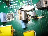
If not would someone with one of these units be able to tell me the value of the following components: transistor TR8, resistor R46 and resistor R47 (near -15volts adjusting pot ) these have been replaced in my dac but not with the same type as the factory.
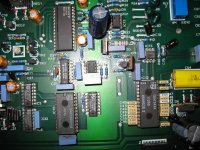
There is also a modification on the board, (near the sony receiver) R20 has 2 resistors a 15Kohm and a 4.71Kohm with a 330uF/63v capacitor from their midpoint to TR4 is this a factory modification?
I have attached some photos which may help.
Thank you in advance for any help
I have just bought a Musical Fidelity Digilog Dac which I intend to modify. I need some help as there is a previous repair which is not as good as I would like.
Firstly does anyone have the circuit diagram/service manual?
If not would someone with one of these units be able to tell me the value of the following components: transistor TR8, resistor R46 and resistor R47 (near -15volts adjusting pot ) these have been replaced in my dac but not with the same type as the factory.
There is also a modification on the board, (near the sony receiver) R20 has 2 resistors a 15Kohm and a 4.71Kohm with a 330uF/63v capacitor from their midpoint to TR4 is this a factory modification?
I have attached some photos which may help.
Thank you in advance for any help
Attachments
Fancy some back-scratching?
Yes - it seems to be a factory mod - mine has exactly the same '330uf/2 resistor' arrangement.
The values you're after are as follows:
TR8: BC414C
R46: 6.8 ohm
R47: 10k
Hope that helps.
Could you help me identify some values?
My Digilog board has several components missing, as follows:
C13
C15
C100
C23
C29
C38
C98
Reg4
Reg5
(I'm presuming these are 15v types, but better safe than sorry!)
Thanks in advance.
Like so much MF gear!
Smiffy, I may be imagining this, but don't you have a schematic for the Digilog?
If memory serves, we had a discussion some years ago about my crazy idea to run the Digilog (or any TDA1541A based DAC, for that matter) at 176.4khz with the Paicfic Microsonics HDCD digital filter chip (I've got a few).
Anyhow, warning anout the PCB tracks noted (thanks) do let me know if you have those values to hand.
component values
Lenin21
Thanks for the information here is what I have found so far
C13 47uF/25V electrolytic
C15 47uF/25V electrolytic
C100 47uF/25V electrolytic
C23 47uF/25V electrolytic
C29 47uF/25V electrolytic
C38 47uF/25V electrolytic is this is next to C39? C38 text is not fully visible?
C98 10uF/35V electrolytic
Reg4 ua7905
Reg5 7805
I can take pictures of the markings of the regs and caps if you like. I think the 15volt rails are regulated by the transistors near the op amps (TR9, TR11 & TR7 for positive 15 and TR8, TR10 & TR12 for the negative) I will only know for certain once I trace out the circuit.
If in doubt trace the +5 and -5v rails from the DAC back to the regs
I emailed the Australian distributer for some information and got nothing back. I will have to trace out the circuit in the future as the toslink output is intermittant on warm up.
Let me know if you need any other values or photos. Oh and my board is version 4 if that helps.
Smiffy thanks for the warning.
Last edited:
If memory serves, we had a discussion some years ago about my crazy idea to run the Digilog (or any TDA1541A based DAC, for that matter) at 176.4khz with the Paicfic Microsonics HDCD digital filter chip (I've got a few).
Have you actually tried that? I'm curious because I'm just starting on a reverse engineering project to work out what goes on inside an SAA7220 in an attempt to find out why NOS sounds much better. If you've found it sounds good with a PMD100/200 that'll be an interesting data point.
No, I've not actually tried it (yet).
It is still generally regarded as the finest digital filter chip ever made though....
It is still generally regarded as the finest digital filter chip ever made though....
It is still generally regarded as the finest digital filter chip ever made though....
Yeah just from reading the datasheet, I get the strong impression those guys know their stuff. And they designed the Berkeley DAC too which has a fine reputation. So when I get around to building my own digital filter I'll start by modelling it on theirs...
I'm curious because I'm just starting on a reverse engineering project to work out what goes on inside an SAA7220 in an attempt to find out why NOS sounds much better.
Not that I'm agreeing with you, but it's easy to work up a rationale for why this might be the case.
1. No-one has yet demonstrated that bit or sampling resolutions greater than 16/44k1 contribute to an improved perceived quality.
2. Post-processing from the native resolution changes the data. There's always the possibility to change it for the worse.
If I was going to upsample I'd do it in software, not hardware. Why add to the hardware design problems? It's another chip.
Upsampling to ease reconstruction is another issue.
Everybody knows that upsampling a photograph is a waste of effort. You might disguise pixellation artifacts in a large print, but only at the cost of a softened image or loss of detail. If you want improved quality, you need a bigger megapixel resolution. Below a certain size of print though, it buys you nothing.
w
Yeah, I've worked up my own rationales too, just wanting to test them. One you haven't mentioned is the extra noise caused by having a sweating (900mW) digital chip right next to the DAC. So I wanna try a lower power filter. I can't follow your point about doing oversampling in software rather than hardware - you're assuming there's already a CPU in the system?
Wakibaki,
I'm with you on the 'upsampling embedded errors is nonsense' argument, but I believe that one of the UK magazines (Hi-Fi News, I think) investigated the issue of word length and sampling rate (from both technical and subjective standpoints, with pleny of measurement to back up their findings). If memory serves, this would have been around the mid to late nineties.
I think the oversall conclusion was that word length has surprisingly little effect on data quality/integrity (from both technical and subjective standpoints) while sampling frequency was found to demonstrate clearly measureable effects, on both fronts.
My memory really is getting worse as I get older (I've started for forget why I walked into a room...) but I'm faily sure about that feature article.
I'm still recovering from a recent visit to the hell that is my loft, but when I recover, I'll launch another expidition and see if I have a copy to scan and post.
Hi,
I too have one of these fantastic dacs which also has that odd repair job/ extra components added in.
I am wondering if anyone else has any issues with their Digilog making a popping noise through the speakers when turning it off (if done before turning off the amp)?
Can anything be done about it? I am just worried that it could damage the amp or speakers.
Johnnz,
I turned the dac of first with the cd player on so the dac was locked and no poping noise.
I'm still having toslink input dropping out problems so will be pulling it apart again and when I do that will try and trace out the mute ccty which should stop the poping noise on turn off.
I hope this helps.
Digilog Mute Circuit
Johnnz,
If you measure the voltage across r48 it should be 0v when the DAC is on but not locked and 3.25v when it locks to the incoming signal.
If you are not getting that then there is a problem.
Let me know how you go and I will try and help but I am only a learner.
Regards
Johnnz,
If you measure the voltage across r48 it should be 0v when the DAC is on but not locked and 3.25v when it locks to the incoming signal.
If you are not getting that then there is a problem.
Let me know how you go and I will try and help but I am only a learner.
Regards
Hi!
What is the output impedance of the Digilog?
Greets.
Tyimo
High enough... at least as measured by a specialized magazine ... 990 Ohm
It's the first time I've heard of this version.Oh and my board is version 4 if that helps.
My Digilog - not long ago I replaced all the electrolytics - is numbered # 3.
Do you know which opamps it mounts?
- Home
- Source & Line
- Digital Line Level
- Musical Fidelity Digilog Dac