Hi Bob, the upgrade BOM requires only components swapping, no trace cuts or bridges.
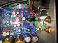
The OPA827 10nF bypass should be mounted on pin 4 and 8 of the browndog.
I've recently discovered that OPA827 changes a lot as time passes in the bass firmness (the bypass is there for that reason), BTW the bypass don't hurt.
Maybe you could start with the bypass and remove it after 50 hours so you can say us if it's really needed...")
Is it just the single 10nF bypass required for this? The latest BOM calls for quantity 2, so is there another 10nF underneath the Browndog as well?
Are you confusing this setup with the mod with on the PCB?
Attachments
Last edited:
Is it just the single 10nF bypass required for this? The latest BOM calls for quantity 2, so is there another 10nF underneath the Browndog as well?
No...
you'll need two because one goes in C1 (SPDIF coupling), the other on the browndog.
Anyone built the shunt on Dario's google drive? As I see the schematic you need to remove the Silmics. Also could it be integrated on board? Not much space on pcb. Also if it's worth the trouble for the outcome.
Of course it worth the effort but the most elegant way is to add a small pcb as there is no so much space on the DAC pcb.
About that TOSLINK module
Like Ch33ta said in this post:
http://www.diyaudio.com/forums/digi...kit-cs8416-ak4393-5532-a-187.html#post3053807
"The CS8416 receiver input pins are not RS-422
compliant; the receiver input absolute maximum
voltage range is ±12 V for the CS8413/14 and
-0.3 V to VL + 0.3 V for the CS8416."
http://www.cirrus.com/en/pubs/appNote/AN339REV1.pdf
"Input signals with voltage levels above VL or
below DGND may degrade performance or damage the part."
http://www.cirrus.com/jp/pubs/proDatasheet/CS8416_F3.pdf
So some toslink modules need TTL -> SPDIF conversion with this dac.
Anyone tried to connect directly to the amp this DAC?
I mean with a virtual ground obtained with a couple of resistor between AVDD and AVSS like someone suggest here.
I've built an F5 clone with no analog input, just toslink and spdif ("Gigawork" DAC ,transformer output). Actually i'm waiting for a board with AK4396 and i would like to test this option...
Off course, ground for the DAC are completely isolated from ground of ampli.
I can give me an answer alone!
I've just tried with my actual CS4398, and the sound is no so good as someone can imagine. I think the absence of LPF degrade the output signal a lot.
The sound is poor, no feelings and with less 3D scene respect to the transformer output.
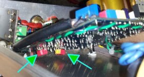
Building this AK4396 from a bare board(except surface mount chip); it's ok for resistors,small capacitor (FKP/FKS) but I am a bit in trouble with electro capacitor:exception C23/24/25 and C38/C39 (they are so big ). Someone can show me on the board where is C14/17/31 C27 C32/33/35 C29/34
Thanks for your help
). Someone can show me on the board where is C14/17/31 C27 C32/33/35 C29/34 Thanks for your help
Hi to everybody.
Is a great thread with great contributors. Very nice reading.
I just bougth the kit unassembled (just waiting to put hands on) and some other parts according ClaveFremen BOM (thanks again to Clave), but trying to save some money, also I'm using some old stuff I have in my spare parts box:
I have a 120 W old psu transformer from a small cheap integrated and dead Sansui amp (55+55W). from the seventies. Transf. is working and in perfect conditions, the secondary is 27-0-27 V but have primary windings in 120, 220 or 240. in my Country outlet ACV is 120, and planning to use mains 120V connected in the 240V primary winding tap, I tested and measured the secondary to be 13.7V and I think this big transformer will go well for the analog supply and will work far away from hysteresys with linear and clean power enough.
Also have some Rubycon 6800 uF 63V caps 85 celsius (japan made) for power supply smoothing and some polypropylene Evox PMR 400V 2.7uF to bypass them.
For the digital supply have found and old wall transformer (without rectifier bridge) from a US robotics external 55Kbps phone modem (do you remember that oldies??), it's 16 watts 120/9 Vac and think is enough power for the digital 3.3V of the two chips that use it. Tested and is in perfect conditions.
I have also some galvanized brass plates 0.25mm thick an will make a enclosure with also some surrounding kind of wood.
Don't want to upset anybody with this, but if somebody can explain me why not to put an optional (on-off, not fixed) upsampling daugther board like CS8421 (like the link at bottom) to have this option enabled. Fikus from lampizator says it's sound is "heaven" in a behringer ultramatch pro. I believe that maybe putting a 6PDT switch like this (link at the bottom) I found on ebay in the path of the R12-R15 resistors (it's not so complicated) we can have a very short wire switch for the digital signals involved (also there are 8PDT switches if want to switch master clock). I only want to hear oppinions and experiences with the electronic upsampling implementation (not the software). Some years ago I bougth a Gigawork (lars) upsampling DAC and modified it. Sound is not bad at all. Thanks in advance for sharing the experiences and apologize for my bad english.
José D'Amico
Stereo Parts Pioneer Switch Push Button Speaker 6PDT | eBay
CS8421 Upsampling Board Suitable for AD1955 DAC Decoder | eBay
hey,
so about to start diy audio, which is going to be awesome<
and am starting with this kit<
just wanted to make sure i was getting the right one, might use that awesome new BOM some time in the future,
so it this the way to go KIT ??
and i was thinking i would get a tube buffer for it, really want to try the tube sound,
any thoughts on using this tube Buffer
the other question, will the R type transformer work with 230V electricity ( im a Aussy) ?

Someone can show me on the board where is C14/17/31 C27 C32/33/35 C29/34
Look in the first pages of the thread. I've posted a pic of the PCB with parts numbering.
sorry for double post, but, all i need to power this a 15*2 R-type transformer ?
That 9Vx2, 15Vx2 transformer is the correct one.
That 9Vx2, 15Vx2 transformer is the correct one.
cheers mate, just ordered, cant wait till mid semester for build time.
am sure i will have heaps more questions
Will receive the kit in two weeks.
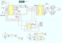
Edited the schematic of this Thread to explain my intentions, maybe is better than write. If someone tried to put switches before on this or a similar board, or already knows if it works (or if this mods can have some trouble), please advice me.
Edited the schematic of this Thread to explain my intentions, maybe is better than write. If someone tried to put switches before on this or a similar board, or already knows if it works (or if this mods can have some trouble), please advice me.
Attachments
okay i think i worked out my own question above(sorry for double post) ,
i have noticed some people with external bridge rectifiers and capacitors, are we supplying rough dc current to it instead of AC for better performance?
Do you understand how a power supply works?
- Home
- Source & Line
- Digital Line Level
- DAC 2496 (AK4393) DAC KIT With CS8416+AK4393+5532