You rec. Cerafine for decoupling of op-amps why not Oscons as per Erin?
Hello Black Stuart, just to clarify. I don't recall saying to use Oscon for decoupling the op amp. In fact I use Elna Silmic.
Silmic and Cerafine have a different sound. Personally I prefer the Silmic and Clave seems to prefer the Cerafine.
I guess its a matter of personal taste.
i think from the erin's original post, that is the seller he or she used.
FYI I am he not she.
I hope this has not ruined my mystique

to erin: thanks for clarifying!!
to bcmbob: thanks for words of advise. i may well go with 'double build' technique, just a bit worried that because i'm a noob with barely any soldering skills, i'll make a hash of the board soldering and de-soldering. i'll check out some youtube videos to see techniques
to bcmbob: thanks for words of advise. i may well go with 'double build' technique, just a bit worried that because i'm a noob with barely any soldering skills, i'll make a hash of the board soldering and de-soldering. i'll check out some youtube videos to see techniques
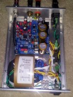
Someone sent a PM asking a photo of the R-core to PCB connection - thinking it might be more complicated than implied.
From upper right down:
1. Simple AC inlet- Green = hot, Black = Common, Gn/Yel = Earth Ground.
2. Fuse holder on Hot leg. Combination units for 1 & 2 can be purchased.
3. Main AC switch on Hot leg.
4. Three position Euro-Style terminal block. For both safety and secure but removable connection to transformer.
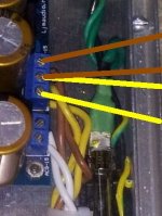
5. Supply wires entering trani at left side.
6. Board power supply wires - White = 9V, Brown & Yellow = 15V.
7. The Red wire is for 230 V applications. The end is covered with heat shrink tape.
8. The Blue wire is an extra 9V lead. Also protected on the end.
Just that simple.
IMPORTANT! It is always recommended to make a secure connection between the (Yellow/Green in this case) safety earth ground to the chassis with three wire AC mains. The only exception is in the use of what is called "double insulated" design where the power is never exposed to the possibility of touch. In the picture there are three potential shock hazards:
1. The bare ends of the fuse. That type should be used with the matching cover. A combo inlet/fuse fixture will eliminate that risk.
2. The unused tab on the two position mains switch needs to be removed and/or insulated. Selection of a switch without the extra pole is recommended.
3. Even though recessed, the terminal block screws could present a hazard from contact with a tool or probe.
4. The BNC S/PDIF connector used in this build is not ground insulated from the chassis. The earth/safety ground does not interfere with the signal.
Take your time and insure no uninsulated mains/AC wire is exposed to air anywhere along its path. If you can see it you can touch it.
From upper right down:
1. Simple AC inlet- Green = hot, Black = Common, Gn/Yel = Earth Ground.
2. Fuse holder on Hot leg. Combination units for 1 & 2 can be purchased.
3. Main AC switch on Hot leg.
4. Three position Euro-Style terminal block. For both safety and secure but removable connection to transformer.
5. Supply wires entering trani at left side.
6. Board power supply wires - White = 9V, Brown & Yellow = 15V.
7. The Red wire is for 230 V applications. The end is covered with heat shrink tape.
8. The Blue wire is an extra 9V lead. Also protected on the end.
Just that simple.
IMPORTANT! It is always recommended to make a secure connection between the (Yellow/Green in this case) safety earth ground to the chassis with three wire AC mains. The only exception is in the use of what is called "double insulated" design where the power is never exposed to the possibility of touch. In the picture there are three potential shock hazards:
1. The bare ends of the fuse. That type should be used with the matching cover. A combo inlet/fuse fixture will eliminate that risk.
2. The unused tab on the two position mains switch needs to be removed and/or insulated. Selection of a switch without the extra pole is recommended.
3. Even though recessed, the terminal block screws could present a hazard from contact with a tool or probe.
4. The BNC S/PDIF connector used in this build is not ground insulated from the chassis. The earth/safety ground does not interfere with the signal.
Take your time and insure no uninsulated mains/AC wire is exposed to air anywhere along its path. If you can see it you can touch it.
Attachments
Last edited:
to erin: thanks for clarifying!!
........ just a bit worried that because i'm a noob with barely any soldering skills, i'll make a hash of the board soldering and de-soldering. i'll check out some youtube videos to see techniques
The technique that has worked best for me goes as follows:
1. Identify the leads of the pieces, one at a time, on the underside of the board. Use lots of liquid flux and solder removal braid to suck up as much solder as possible. You can see it flow to the braid from the joint. Only then remove the piece as less solder will collect in the via between top and bottom. Leads connected to large ground planes will require more heat.
2. When everything is removed, go back over all the pads with flux/braid to get the remaining solder off as best you can. Take care to not use excessive pressure as the braid can be abrasive. Just drag the braid slowly while keeping the iron above the pad.
3. If the holes are plugged use a junk resistor lead or small solid wire of the same size as the via to clear it. Heat the wire and pad together and a gentle pressure will make a penetration and the excess solder will transfer to the dummy lead. You may have to repeat several times cleaning the wire with a file or fine sandpaper. If the solder cools there is a risk of pulling out the via and/or lifting a trace. Just use very small movements and insure the solder is hot before extraction. Do not rush this step.
4. When all holes are clear, I use rubbing alcohol and a toothbrush (and a fingernail) to remove all the flux. Then I spray Dow Scrubbing Bubbles Cleaner on the bottom and agitate again with a brush. I use a wet/dry vacuum to remove that cleaner because paper and cloth towels leave a lot of lint on the remaining stubs/joints on the board. Use what you have.
5. Not necessary, but I use a clean shoe brush to polish things and impress myself of my good work.
It's my preference to remove all pieces I plan to replace before adding all the new items. If you want to do one piece/section and a time and test/audition, the above steps are still recommended.
Check Google again for solder removal braid videos.
Last edited:
I also agree with Bob. I built the DAC as stock so that I could quickly replace a DAC on my PC that failed a while back. The improvement in sound quality over the line out on my sound card was huge. I am now going to order a blank board and install Dario's Mods and experiment. I have on several occasions ordered the wrong part from Mouser so I can agree with that point too. Its hard to justify paying $9 shipping for a .20 resistor.
hi dario (or anyone else who knows for sure)...
i ordered item 714682 from distrelec sweden, thinking they were right for R24 - R34.
however, whilst labelling/checking components that have arrived, i see they're 2.43Kohm 1/4W(which suit original board, as per BOM).
BUT, the modified BOM says 2.2Kohm 1/4W. i'm guessing it wouldn't do to try these resistors and just write them off, ordering 2.2Kohms instead.
is this right, i shouldn't use what i have already? (the 2.43K's)
i ordered item 714682 from distrelec sweden, thinking they were right for R24 - R34.
however, whilst labelling/checking components that have arrived, i see they're 2.43Kohm 1/4W(which suit original board, as per BOM).
Don't worry... 2.4K is the right value... PRPs are indicated as 2.2k simply because they're not available as 2.4k from PCX.
A lot happened yesterday - I opened an email thinking it was about a shipment from the USA re. DHL - it was'nt, it was a 'ransom ware' attack (lots of effing and blinding), luckily Panda Cloud software neutralised it on start-up today.
Then the package from Along arrived much quicker than I was expecting.
For anyone who is thinking of buying a complete assembled kit or as seperate items which I chose - it was very well packed and I thought the quality of the chassis was as good as any chassis supplied with commercial equipment. The beauty of this chassis is that it comes in two parts and by just undoing the top screws front and back you can lift off the top half which gives complete access to the innards - why don't commercial gear use the same style. It means that I can adopt the best cabling technique which is - the best connector is no connector at all, aka, I can solder directly from PCB to PCB, just using rubber grommets to protect the dialectric entering the backplates.
The soldering of i/cs on both boards was first class and though there are no + or - lettering just by turning the board over it's crystal clear which way to solder polarised caps.
Another big plus is that with the supplied chassis there is plenty of room to solder off-board eg. big PSU caps.
Negatives - the supplied on-off switch has a rectangular shape that does'nt match the round hole in the faceplate - trying to get this to work meant that I broke the very brittle plastic and need to contact Along about a new on-off switch assembly and or buy a new one. Also 2 brass stand offs were missing from the packet of parts - I seem to have lots of spare screws.
All-in-all, Along is presenting a very well thought out product, which importantly is well packaged - don't ever under-estimate this important point
- yesterday I received a valve I had bought on Ebay.UK and it was badly packaged - one direct whack and the bottle would have been broken.
Dario - you mentioned that if you were to do more on this DAC it would be in the PS - would you care to tell us what you might do? I was thinking about building a bridge of Shottkies or others as well as increasing capacitance though not voltage for the PSU caps?
As if I needed reminding - I bodge soldered Z foil shunt Rs from Alps Blue to PCB in my Bada power hybrid amp - wow, suddenly the sound stage opened up, loads more detail and voices became almost holographic, they will be with the other mods I'm going to do - the point is that I shall use some Z foils in this DAC along with the PRPs soldered on pins - vamos a ver.
hi dario, sorry to trouble you again. i'm trying to do this in a complete novice manner but without troubling you or my dad/step dad too much.
i've bought 2 x nichicon 100uF 50V from mouser, part number 647-UFW1H101MPD for positions C3 and C27 according to the BOM.
however, going through my checklist, i see that C3 is 100uF 50V, but C27 is 10uF 100V.
is this a typo or do i need to order 10uF 100V?
also, C3 is shown on the schematic as 100nF non-electrolytic. i'm a little confused
i still have parts on back order at mouser, so i can still order from them at no extra cost, just need to know the right components!
Hi James,
a good question and it's easy to see why you asked it and I'm glad you did as I hav'nt put my parts order in yet.
I'm surprised that no one mentioned that Along's PCB has through hole plating, a huge plus if you have to desolder.
I broke the on-off switch because it has a rectangular face to fit into a round hole and the plastic is extremely brittle and it broke whilst I was trying to trim it to fit. OK take the positive from the negative - it's never a good idea to have mains wiring alongside signal components so I am going to enlarge the cut-out for the IEC plug and fit a 3-in-1 switch/fuse/plug there.
Dario - you mentioned that if you were to do more on this DAC it would be in the PS - would you care to tell us what you might do? I was thinking about building a bridge of Shottkies or others as well as increasing capacitance though not voltage for the PSU caps?
Soft recovery or Shottkies are a good idea, I don't think more capacitance is a good idea...
is this a typo or do i need to order 10uF 100V?
You're right...the Mouser order code is not the right one, it should be read 647-UFW2A100MED.
I've just updated the Google Docs BOM.
BTW for whom already bought the 100uF FWs: don't worry the 100uF value is also good for that posistion.
I have just ordered a bare board but the CS4398. Looking at Darios BOM it is evident that some of the dac pins and/or capacitors have changed. The schematic can be found here:
http://www.diyaudio.com/forums/digital-line-level/211321-dac-cs4398-cs8416-cm102s-2.html
Looking at the 4 electrolytics around the dac, I am trying to assign them to the AK4396 board but could do with some clarification please.
C32 and C33 @ 10uF seem to be the same on both boards.
C30 10uF on the 4396 might become C35.
C35 on the 4396 appears notto be fitted.
C45 100uF is on 4398 but maybe not on the 4396
On Dario's BOM, C30 is a larger 100uF solid cap. The other 3 remain 10uF but changed for Cerrafines?
So I have bought 4 100uF Nichicon LF caps from slease-bay. One was for C45 but could I use the other three for C32, C33 and C35 on the CS4398 board without any detriment?
I was not going to fit any bypass caps to these 4 positions.
Thanks in advance.
I have just ordered a bare board but the CS4398. Looking at Darios BOM it is evident that some of the dac pins and/or capacitors have changed.
It's simply because they're different products... my BOM is for the AK4396 MINI2496.
Hi Dario,
If I use Shottkies to build bridges are these the right values - 2A/1000V? I have postioned all the components on the board (without soldering) and I see that I shall have to hotglue the 3 x PS caps to the chassis, only then can I build the Shottkie bridges.
I see that the Fischer heatsink is for using with the + reg. but none for the - regs, does that mean that the - regs generate no significant heat? I ask because in my two hybrid amps it is the 3 - regs that are heatsinked and not the 2 + regs.
Ditto the question from Darpmalone.
Stuart
- Home
- Source & Line
- Digital Line Level
- DAC 2496 (AK4393) DAC KIT With CS8416+AK4393+5532