I have a general question about these DAC boards as I am considering purchasing one to play with.
Several vendors show what are supposed to be FFTs and frequency response plots of the DACs in operation.
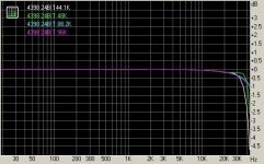
The attachment is typical of the frequency response plots I see.
Note the response for 44.1KHz and 48KHz sample rates go beyond 40KHz for the -3dB point! Kind of a neat converter to get around Nyquest.
Can any of the data seen be trusted?
In particular I am interested in the CS8416 plus CS4398 boards and as questionable as the plots are I'm wondering how good they really are.
Thanks.
Several vendors show what are supposed to be FFTs and frequency response plots of the DACs in operation.
The attachment is typical of the frequency response plots I see.
Note the response for 44.1KHz and 48KHz sample rates go beyond 40KHz for the -3dB point! Kind of a neat converter to get around Nyquest.
Can any of the data seen be trusted?
In particular I am interested in the CS8416 plus CS4398 boards and as questionable as the plots are I'm wondering how good they really are.
Thanks.
Attachments
I would like to check your Shunt reg on the AK4396 5v Ana ,i have a question about the BD 139 .
Can i replace it by an equivalent smaler ?
Hi Serge,
if you mean physical smaller the direct equivalent is BC639 (better the -16 version).
BTW any bipolar with hfe > 120 and power ratings >625mW should do .
I seem to have a dead DAC on my hands....
Power, 96k, error lights come on, 96K goes off when SPDIF is plugged in, error light flickers when the CD is spooling up and goes out when the CD plays.
just no sounds...
Transformer voltages are OK.
I swapped the op-amp for the original, it being the only thing which is socketed, but same results as expected.
My principle DAC one of Peter Daniels NOS DAC (I love it) works in the same slot with all the same cabling (all other thing equal).
Can any one spot anything stupid?
Do those symptoms mean anything to anyone? (Apart from 'it's fu--ed'!)
Bill
Remove the green/yellow (screen) from the phono outputs then wire the spare green and black wires together on the 9 volt input .eg: black with black and green with green. The voltages should be higher than you show 8.5v ac 9.5v DC these should be higher, wiring the two windings together will give you more current.
Here's an unbalancer using miniature 6n16b tubes.... the blog is in italian (but you can use google to translate it into english.
Valvole & Audio: UNBALANCER Project
Does anyone know where I can get a spice simulator for tubes?
LTSpice from Linear Technology. It is free, and there is considerable on line support.
Remove the green/yellow (screen) from the phono outputs then wire the spare green and black wires together on the 9 volt input .eg: black with black and green with green. The voltages should be higher than you show 8.5v ac 9.5v DC these should be higher, wiring the two windings together will give you more current.
Thanks I'll try that later. I did try removing the earth/ground/screen from the phono outputs, I keep trying everytime I change something else.
OK on the bench but in the final config. I think phono earth should be earthed.
More later...
Thanks
Bill
Hi Serge,
if you mean physical smaller the direct equivalent is BC639 (better the -16 version).
BTW any bipolar with hfe > 120 and power ratings >625mW should do .
Thanks Dario
Serge
Hi Serge,
if you mean physical smaller the direct equivalent is BC639 (better the -16 version).
BTW any bipolar with hfe > 120 and power ratings >625mW should do .
hey Dario, can we see some pictures of your DAC after the shunt regs mod?
it just seems with all that components, it seems a little pushing it to mount them all on the board
I turned it on today!
Usually I'm always pessimistic when it comes to the first listen of any of my devices - I always expect them to sound bad. So I plugged the S/PDIF, turned it on, played music and
WOW! I had one of these moments staying with the mouth open for minutes. Played song after song, this thing sounds so great. At thirst, there was a tiny weirdness in the sound, but it seemed to get away with time, maybe burning in. My face went in tears when I played Three Wishes by Roger Waters, never heard it sound this way.
So here's a "resume" of the description of my DAC
-6Н1П input tubes (3mА -1,5V)
-6Н6П output (15mА -2,5V)
-interstage coupling К40-У9 PIO russian caps without the metal casing
-output coupling ЕТО-3 AgTa wet miltary grade russian caps
-Tesla resistors, and carbon composite
-PSU: Cf LC LC LC RC Cf=50uF L=5H, C=4uF, R =1k
-pine chassis with shellac coating
-Salas shunt reg for the analog DAC part
-separate cables for DAC PSU, heater PSU and B+
-option to turn the heater before the B+
Things to do:
-stabilization of first stage B+ using voltage stabilizers OA2
-USB->I2S board inside close to the DAC board. The DAC will become USB compatible.
-Another Salas shunt for the I2S PSU
-Removing the electrolyte cap from the PSU and making it electrolyteless.
Remove the green/yellow (screen) from the phono outputs then wire the spare green and black wires together on the 9 volt input .eg: black with black and green with green. The voltages should be higher than you show 8.5v ac 9.5v DC these should be higher, wiring the two windings together will give you more current.
Well... I tried that and the transformer physically buzzes horribly!
even after unplugging signal input and output
Also no LED's on teh board light up.
I won't hazard any guesses because I am a 'join the dots' player in this forum.
Hoping my mistakes may help others to avoid them...
Is that a yellow Ducati in your Avatar Hotiron? Picture is too small so I can't ID the bike.
OK, so I was lying... I speculate...maybe I have a duff transformer (or I fried the transformer)?
Where can I find out all about testing transformer health in a jiffy?
Best regards,
Bill
Last edited:
hey Dario, can we see some pictures of your DAC after the shunt regs mod?
I've yet to try it... so no pics
Maybe this WE
it just seems with all that components, it seems a little pushing it to mount them all on the board
I think that an external PCB is needed.
I'll start trying it on breadboard and if it works as intended I'll probably make a PCB.
Bill,Are you using a "dim bulb" tester in your setup rig?
I did use a dim bulb tester in line when I first tested the transformer before first plugging it into the board. The bulb never lit up at all and VAC outputs all seemed fine.
Very good advice though, and I will put the dim bulb safety factor back into the mains AC power supply line right away.
Thanks for the reminder.
Bill
Last edited:
I stumbled across this unit this morning. Has some interesting info at the design link on the page. Has anyone tried it?
S/PDIF Bridge | USB to SPDIF cable | USB DDC
S/PDIF Bridge | USB to SPDIF cable | USB DDC
I've yet to try it... so no pics
Maybe this WE
I think that an external PCB is needed.
I'll start trying it on breadboard and if it works as intended I'll probably make a PCB.
Hi Dario ,
What about capacitors in your shunt reg ?
Thanks
Serge
What about capacitors in your shunt reg ?
Hi Serge,
the idea is to re-use the ones on board.

My kit arrived also (1.5 weeks from Singapore to the Netherlands).
I have some questions:
* The supplied resistors are 1% versions. I want to change them to a metal film 0.1%. Is that a good or bad idea?
* The smoothing capacitors (2200 uF) are made by Toshiba. No other markings on them. Should they be changed? Can any capacitors (like
10.000 uF, Philips or Panasonic) be used? The little ones (220 uF) are made by Nichecon FW types.
* I will replace the supplied L7812 by MC7812CTG
* The 100 nF capacitors are orange, drop type. No further markings. Also other capacitors are square, white or blue. No markings. Should or can they be replaced by sibatit capacitors?
* The 10 uF capacitors are gold marked, "W6C PET" marking. Good enough? Or tantalum is better?
* On the PCB I see some very small holes, and no marking on them. Are that VIA's to the other plane (bottom / top)
Haik
- Home
- Source & Line
- Digital Line Level
- DAC 2496 (AK4393) DAC KIT With CS8416+AK4393+5532