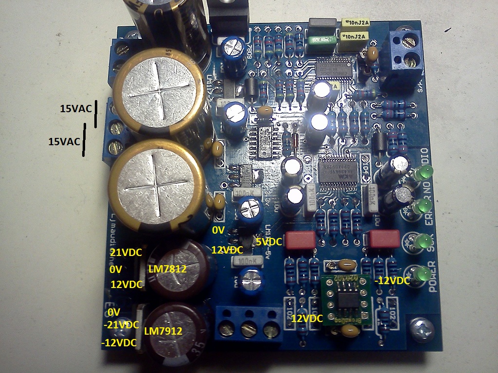
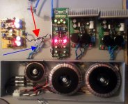
Here are bigger pics including the legend on the Transformer.
I think the connection should be blue (15) - black and blue (0) - black (15)
Exactly.
According to the label you shoud use (they should be in pairs)
BLU1 -> 15V
BLK1/BLU2 -> 0V
BLK2 -> 15V
Usually the first color in pair is phase and the second is neutral
looks interesting, dario.. how can we make the +9V version?
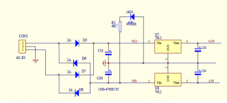
The regulator is pretty easy to adapt, you simply change the zener considering that the output voltage is the zener voltage with 0.6V added.
Also you should calculate the maximum required current, increase it by 15mA and use that current to calculate current setting resistor (1.25V/current).
But I don't know if in digital applications it is any better than a OnSemi MC7809.
indeed it's much simplier, though have you done any face to face comparison with Salas? Also why do you think it would be an overkill for opamp?
No, Salas shunt is for sure superior.
I think that probably a Salas shunt is overkill since opamps have high PSRR, while in a simple discrete circuit, like the DCB1, PSRR is much lower.
"Exactly.
According to the label you shoud use (they should be in pairs)
BLU1 -> 15V
BLK1/BLU2 -> 0V
BLK2 -> 15V
Usually the first color in pair is phase and the second is neutral"
Thanks Dario!
I hooked together the/a blue black pair with 0 continuity as per apoopoo999's kind advice, but I still have no analogue output.
I'm sad now!
Burst another bubble
Do a get an award for 'DIY Dumbo of the week'?
As I see it there are three logical possiblilities ....
1) I haven't fixed the AC supply issue correctly.
2) I damaged some/several components by applying AC power incorrectly.
3) There was more than one problem/error in the first place, and there is another error(s) still to correct.
I think some of my peers on this forum will know if 2) above is likely?
As always I appreciate any advice you can offer peeps.
Bill
Last edited:
I hooked together the/a blue black pair with 0 continuity as per apoopoo999's kind advice, but I still have no analogue output.
I'm sad now!
Burst another bubble
Hi Bill,
just to be sure measure (trsanformer only) AC from BLU1 and BLK1/BLU2 (it should measure 15Vac) and from BLK2 and BLK1/BLU2 (it should also measure 15V)
If it's so you wired correctly the transformer.
Probably you burnt one or both the MC7x012.
Try to measure Vdc on them.
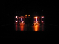
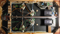
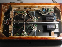
Some new photos. Today I will play with the anode voltages:
http://store.picbg.net/pubpic/D0/84/bf9a61bc242bd084.jpg
http://store.picbg.net/pubpic/F7/89/8fea21e64246f789.jpg
http://store.picbg.net/pubpic/7B/84/97c0af271ef87b84.jpg

http://store.picbg.net/pubpic/D0/84/bf9a61bc242bd084.jpg

http://store.picbg.net/pubpic/F7/89/8fea21e64246f789.jpg

http://store.picbg.net/pubpic/7B/84/97c0af271ef87b84.jpg
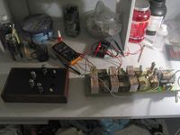
Billo - A shot in the dark - I had a very strange problem when wiring my JC-2 pre (yellow board). If both 0V wires were connected to the PCB the unit would not function. After combining them in a terminal block and running a single wire to the board, everythings works. Makes no sense to me ( I was going to post about it) but believe me, it was the only way I could get the pre to work.
Might be worth a try. In the photo the Lighter Note is also powered by the same toroid, but the problem was there even when that circuit was not involved.
Might be worth a try. In the photo the Lighter Note is also powered by the same toroid, but the problem was there even when that circuit was not involved.
Attachments
Last edited:
Hi Bill,
just to be sure measure (trsanformer only) AC from BLU1 and BLK1/BLU2 (it should measure 15Vac) and from BLK2 and BLK1/BLU2 (it should also measure 15V)
If it's so you wired correctly the transformer.
Probably you burnt one or both the MC7x012.
Try to measure Vdc on them.
Thanks for your help Dario.
I had measured VAC from the transformer before risking applying power to the board (I thought).
I didn't take notes sadly, but I thought I had closer to 15 VAC in my original blue1 - black1/black2 - blue 2 configuration....
Supply voltage here is just a little under 100 VAC/@60Hz.
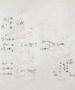
Here is a low res picture of my notes, red is my actual measured voltages on my DAC.
Bill
Attachments
Last edited:
Here's an unbalancer using miniature 6n16b tubes.... the blog is in italian (but you can use google to translate it into english.
Valvole & Audio: UNBALANCER Project
Does anyone know where I can get a spice simulator for tubes?
Valvole & Audio: UNBALANCER Project
Does anyone know where I can get a spice simulator for tubes?
It's not indicated but do you have the 3.3 and 5 volt on the other regs?Here is a low res picture of my notes, red is my actual measured voltages on my DAC.
Bill
All seem OK as per attached picture (small print sorry).It's not indicated but do you have the 3.3 and 5 volt on the other regs?
Bill, any of the chip getting very hot?
I'll check that out, I haven't left the thing on too long for fear of smoking a chip.
I can start hunting down the signal trace with a scope...?
Don't really know what I'm doing though...
Thanks everyone.
Bill
Attachments
All seem OK as per attached picture (small print sorry).
Just to point out the picture in my previous post is from Dario with my measured values annotated. It isn't my board.
If you click and then click the full size button bottom left it is readable.
Thanks everyone.
Bill
Just to point out the picture in my previous post is from Dario with my measured values annotated. It isn't my board.
If you click and then click the full size button bottom left it is readable.
Thanks everyone.
Bill
Did you try putting back the 5532? I managed to kill 1 ak4396 and 1 ak4395 so youre not the only one

No, Salas shunt is for sure superior.
I think that probably a Salas shunt is overkill since opamps have high PSRR, while in a simple discrete circuit, like the DCB1, PSRR is much lower.
do you mean that there is no point and it doesn't worth to make separate salas just for opams (ex. some simple headphone amp or opamp output of CD player, etc). I was wandering is it ok to use your shunt with other regs - 7808-7812 or add some variable R to LM317 version?
Attachments
All seem OK as per attached picture (small print sorry).
Bill, the values around the 9V regulator seems way too low but it shouldn't be a problem...
Now, apart no analog output, the leds behave correctly?
do you mean that there is no point and it doesn't worth to make separate salas just for opams (ex. some simple headphone amp or opamp output of CD player, etc).
Not as a general rule.
Probably a Salas shunt would sound better than my shunt even with opamps but I suppose difference wouldn't be much thanks to opamps PSRR, IMHO.
But I didn't any direct comparison.
I was wandering is it ok to use your shunt with other regs - 7808-7812 or add some variable R to LM317 version?
It's not clear... do you mean using 78xx instead of LM3x7 in current sources?
My AK4396 chips have arrived today!! Hopefully tonight this DAC will be singing! This is what I did yesterday:
http://store.picbg.net/pubpic/83/FF/68886e98d54483ff.png
http://store.picbg.net/pubpic/D2/89/566d431f2d6dd289.jpg

http://store.picbg.net/pubpic/83/FF/68886e98d54483ff.png

http://store.picbg.net/pubpic/D2/89/566d431f2d6dd289.jpg
It's not clear... do you mean using 78xx instead of LM3x7 in current sources?
hi Dario,
just small improvement over existing opamp PSU in another diy dac (WM8740). As there is no place in the box for another salas shunt, your mod looks very nice.
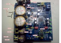
The regs are 7812 & 7912, so I thought whether could I add marked part (att) between reg and cap? Is there any calculation for R104 & D105 or it's already done in accordance to BD139?
Attachments
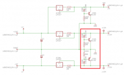
The regs are 7812 & 7912, so I thought whether could I add marked part (att) between reg and cap?
No, they replace completely the 7x12s.
And you shouldn't omit the LM317 CCSs... you can replace them with current setting resistors but you loose 50% of the performace improvement.
Is there any calculation for R104 & D105 or it's already done in accordance to BD139?
You must choose the zener voltage (Vout = Zener voltage + 0.6V) and size the current setting resistors R101/R201 (1.25V/R=Iout + 15mA).
R104/R204 are sized for a 500mW zener.
Billo - A shot in the dark - I had a very strange problem when wiring my JC-2 pre (yellow board). If both 0V wires were connected to the PCB the unit would not function. After combining them in a terminal block and running a single wire to the board, everythings works. Makes no sense to me ( I was going to post about it) but believe me, it was the only way I could get the pre to work.
Might be worth a try. In the photo the Lighter Note is also powered by the same toroid, but the problem was there even when that circuit was not involved.
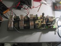
Hi Bob,
It might be that you made a simple mistake. I see the cables (for secondary voltages) are same color. The secondary windings are actually polarized.
Not like positive or negative, but they have a "beginning" and an "end" of the winding. It does not matter how you connect them, as long as the cable to the center point of the pre-amp or DAC have two cables.
One should be "winding 1 END" and the other should be "winding 2 BEGIN". The beginning of a winding is often shown with a dot or a marking.
If you do that wrong, then they compensate themselves, resulting in 0 V (or very close to zero). If that happens, swap two cables from ANY winding.
Bill, the values around the 9V regulator seems way too low but it shouldn't be a problem...
Now, apart no analog output, the leds behave correctly?
Not as a general rule.
Probably a Salas shunt would sound better than my shunt even with opamps but I suppose difference wouldn't be much thanks to opamps PSRR, IMHO.
But I didn't any direct comparison.
It's not clear... do you mean using 78xx instead of LM3x7 in current sources?
Hello Dario ,
I would like to check your Shunt reg on the AK4396 5v Ana ,i have a question about the BD 139 .
Can i replace it by an equivalent smaler ?
Thanks
Serge
- Home
- Source & Line
- Digital Line Level
- DAC 2496 (AK4393) DAC KIT With CS8416+AK4393+5532