Unfortunately that Jim's Audio pcb is not for a Broskie unbalancer.
Apparently just a simple preamp, with a dual valve per channel. With Jim's audio we can never know because they hide the schematics.
It would be great to a get a Broskie kit from eBay.
Sorry to disagree with you 50AE, but a pcb is always better than a point to point circuit. Designing and making one is not such a big deal, particularly today.
I just counted 26 solder points on a single channel for the Broskit, with high voltages and all, I don't think is safe to do such a thing.
Unfortunately that Jim's Audio pcb is not for a Broskie unbalancer.
Apparently just a simple preamp, with a dual valve per channel. With Jim's audio we can never know because they hide the schematics.
It would be great to a get a Broskie kit from eBay.
Sorry to disagree with you 50AE, but a pcb is always better than a point to point circuit. Designing and making one is not such a big deal, particularly today.
I just counted 26 solder points on a single channel for the Broskit, with high voltages and all, I don't think is safe to do such a thing.
it's actually the other way around. point to point should sound BETTER. there is a reason why high end tube companies prefer to make their amp point to point
") . but if we count the other factor, which is safety, then yes, pcb would be the wiser choice
. but if we count the other factor, which is safety, then yes, pcb would be the wiser choiceWhile both have their pros and cons, I prefer the point to point for tubes, because:
-there is freedom and less limits of imagination for your layout
-it is more simple to realize, a properly made PCB can be tricky to make
-more simple to modify (removing components for a listening test)
-it should sound better, because the freedom in PtP you have
About safety, it's good to think about it.
A few hours ago I built another Salas 5V shunt and configured both to work. One will be for analog part of the DAC and the other for the digital part of the USB->I2S.
I think the best of both worlds can be arranged. You do need a flat surface to assemble the parts and solder p2p, right?
If you design a pcb to be used on the "component side", you can still use large pads to put solder in and then solder the other part on same solder. What you won't have is tracks, but the wires will be soldered directly to each other.
I still think, and will continue to use, that pcbs are better than p2p, except of course for experimenting. But one thing should be considered as a directive: distance between parts should be minimal.
Dead DAC
I seem to have a dead DAC on my hands....
Power, 96k, error lights come on, 96K goes off when SPDIF is plugged in, error light flickers when the CD is spooling up and goes out when the CD plays.
just no sounds...
Transformer voltages are OK.
I swapped the op-amp for the original, it being the only thing which is socketed, but same results as expected.
My principle DAC one of Peter Daniels NOS DAC (I love it) works in the same slot with all the same cabling (all other thing equal).
Can any one spot anything stupid?
Do those symptoms mean anything to anyone? (Apart from 'it's fu--ed'!)
Bill
I seem to have a dead DAC on my hands....
Power, 96k, error lights come on, 96K goes off when SPDIF is plugged in, error light flickers when the CD is spooling up and goes out when the CD plays.
just no sounds...
Transformer voltages are OK.
I swapped the op-amp for the original, it being the only thing which is socketed, but same results as expected.
My principle DAC one of Peter Daniels NOS DAC (I love it) works in the same slot with all the same cabling (all other thing equal).
Can any one spot anything stupid?
Do those symptoms mean anything to anyone? (Apart from 'it's fu--ed'!
)Bill
Attachments
Can any one spot anything stupid?
Do those symptoms mean anything to anyone? (Apart from 'it's fu--ed'!
Hi Bill,
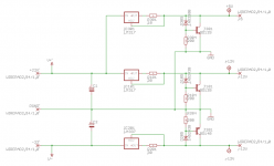
is the 15-0-15 wired correctly?
It seems wrong...
Can you post bigger pics?
nice to see you Dario should not you sleep by now?
btw are you done with the shunt-psu for this dac you have been designing?
Quite, here is 1:07AM...
I've just received all the needed parts (hopefully), I hope to give it a try next week end.
I've been busy with the My_Ref Fremen Edition and modding a My_Evo.
Didn't knew you where fidling around with a shunt psu for this DAC?
I've yet to try it:
It gave me great results with the FE and it's much simpler (and cheaper) than a Salas shunt that, BTW, it's probably overkill for an opamp.
What's a My_Evo?
It's Mauro Penasa's successor of the My_Ref but unlike the latter it's not a public design.
Basically it's a My_Ref with double current pump, DC-servo and a different compensation scheme.
Attachments
Are your 3.3 and 5volt regs OK?I seem to have a dead DAC on my hands....
Power, 96k, error lights come on, 96K goes off when SPDIF is plugged in, error light flickers when the CD is spooling up and goes out when the CD plays.
just no sounds...
Transformer voltages are OK.
I swapped the op-amp for the original, it being the only thing which is socketed, but same results as expected.
Bill
It's Mauro Penasa's successor of the My_Ref but unlike the latter it's not a public design.
Basically it's a My_Ref with double current pump, DC-servo and a different compensation scheme.
looks interesting, dario.. how can we make the +9V version?
Hi Bill,
is the 15-0-15 wired correctly?
It seems wrong...
Can you post bigger pics?
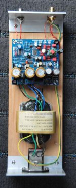
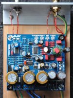
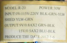
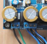
Here are bigger pics including the legend on the Transformer.
I wired the transformer into a 'chocolate block' connector on the bench first and confirmed the voltages, but I'll be happy enough if I made a silly mistake with the wiring and the thing still works afterwards..
.The blue black and green black pairs were tied up when the transformer arived.
I wired the both two blacks (from the blue black pairs) into the 0 of the 15-0-15 connection... I think
I appreciate the help, thanks.
Bill
Attachments
Here are bigger pics including the legend on the Transformer.
I wired the transformer into a 'chocolate block' connector on the bench first and confirmed the voltages, but I'll be happy enough if I made a silly mistake with the wiring and the thing still works afterwards..
The blue black and green black pairs were tied up when the transformer arived.
I wired the both two blacks (from the blue black pairs) into the 0 of the 15-0-15 connection... I think
I appreciate the help, thanks.
Bill
I think the connection should be blue (15) - black and blue (0) - black (15)
I think the connection should be blue (15) - black and blue (0) - black (15)
I second that, actually it wont really matter about the color, you need to test the wires with a meter to be sure that the 2 wires u tie together for 0 dont have continuity
Last edited:
I've yet to try it:
It gave me great results with the FE and it's much simpler (and cheaper) than a Salas shunt that, BTW, it's probably overkill for an opamp.
cheers Dario!
indeed it's much simplier, though have you done any face to face comparison with Salas? Also why do you think it would be an overkill for opamp?
I think the connection should be blue (15) - black and blue (0) - black (15)
I second that, actually it wont really matter about the color, you need to test the wires with a meter to be sure that the 2 wires u tie together for 0 dont have continuity
Thanks folks I'll check that out later.
Hope I haven't fried anything!
Bill
- Home
- Source & Line
- Digital Line Level
- DAC 2496 (AK4393) DAC KIT With CS8416+AK4393+5532