Transformers & EMI shielding
Ok, so someone mentioned the possible differences between E/I transformers, Torroids & R-core types and whether it's measurable. Prudence in design was mentioned too.
There are additional factors to include within the EI and R-core designs such as whether mu-metal EMI shielding (commonly utilised around AV speaker magnets) is incorporated or not. That may very well give rise to differing noise measurements / perceived sound quality.
To answer Noisan's previous question either Mu-metal or grounded copper screening plates could be incorporated between pwr supply section & dac board - I recall how some of Marantz/sony/philips top end Transport & DtoA models have compartments screened by copper plate & chassis
Also, if you do a search on this forum you'll find Peter Daniels experience of bonding a copper plate on top of & between dac i.c's and the grounding thereof
It's funny that this should arise in the postings now as this was the next mod I was looking to implement on my latest dual-dac kit (the CS4398 with VFD display)
-Andy-
What is a good shield between the tranny and the board? An aluminium plate cross the enclosure? or any better idea?
Ok, so someone mentioned the possible differences between E/I transformers, Torroids & R-core types and whether it's measurable. Prudence in design was mentioned too.
There are additional factors to include within the EI and R-core designs such as whether mu-metal EMI shielding (commonly utilised around AV speaker magnets) is incorporated or not. That may very well give rise to differing noise measurements / perceived sound quality.
To answer Noisan's previous question either Mu-metal or grounded copper screening plates could be incorporated between pwr supply section & dac board - I recall how some of Marantz/sony/philips top end Transport & DtoA models have compartments screened by copper plate & chassis
Also, if you do a search on this forum you'll find Peter Daniels experience of bonding a copper plate on top of & between dac i.c's and the grounding thereof
It's funny that this should arise in the postings now as this was the next mod I was looking to implement on my latest dual-dac kit (the CS4398 with VFD display)
-Andy-
Hi,
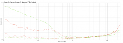
I just measured the dac with the ebay R-Core(2x9v+2x15V) and also with two 30VA R-Core (one is 2x9v, the other 2*12V), and there are small differences in the sub 1000Hz range. In red is the ebay R-core and in green the two 30VA R-cores. In solid the 2nd Harmonic Distortion and in dotted the third (in percentage) across the audio freq range.
At least it shows that transformer difference is measurable.
Caution with the ebay r-core to plug the 15V in phase beacause the wires for the two secondaries are the same color (yellow and brown).
Time for listening now...
Attachments
Hallo
I am a total Neewbe, so sorry for asking a stupid question.
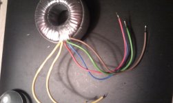
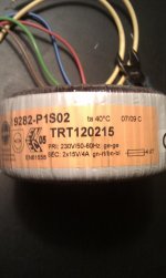
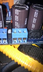
I have just soldered the ebay DAC but, have trouble finding out, how to connect to the transformer. The one of the two "power indputs" have 3 connections. I have a traffo whith 2x15Vac, i was planning to youse for this project. How do i connect the 4 wires from the traffo ? Please se my pictures.
I am a total Neewbe, so sorry for asking a stupid question.
I have just soldered the ebay DAC but, have trouble finding out, how to connect to the transformer. The one of the two "power indputs" have 3 connections. I have a traffo whith 2x15Vac, i was planning to youse for this project. How do i connect the 4 wires from the traffo ? Please se my pictures.
Attachments
Hi,
I just measured the dac with the ebay R-Core(2x9v+2x15V) and also with two 30VA R-Core (one is 2x9v, the other 2*12V), and there are small differences in the sub 1000Hz range. In red is the ebay R-core and in green the two 30VA R-cores. In solid the 2nd Harmonic Distortion and in dotted the third (in percentage) across the audio freq range.
At least it shows that transformer difference is measurable.
Caution with the ebay r-core to plug the 15V in phase beacause the wires for the two secondaries are the same color (yellow and brown).
Time for listening now...
How can you tell if they are in phase or not if they are both in the same color?
How can you tell if they are in phase or not if they are both in the same color?
I used a two channel scope. I plug a yellow and a brown together for ground and the other yellow and brown to scope channels.
To be more precise, I plug the transformer to the dac with the wires that are in opposite phase.
Silver84.
You have to search the web for the connection diagrams for your transformer.
I found this.
http://www.display.nl/components/com_virtuemart/shop_image/tekening/02.04.12015.tek.jpg
You have twin secondaries.
The red and brown should be connected together as the lower drawing shows.
This becomes the 0 volts and should be connected to the centre terminal of the three way block.
The other two wires connect either side of it.
If you are only using one transformer, you have to join two solder dots underneath the board.
This connects the other bridge rectifier to the wires you have connected.
Hallo
I am a total Neewbe, so sorry for asking a stupid question.
I have just soldered the ebay DAC but, have trouble finding out, how to connect to the transformer. The one of the two "power indputs" have 3 connections. I have a traffo whith 2x15Vac, i was planning to youse for this project. How do i connect the 4 wires from the traffo ? Please se my pictures.
You can try by putting together 'gn' and 'bn' wires for AC ground (in the center of the triple blue connector) and 'rt' wire to another connector, and 'bl' to the third connector. 'ge' and 'ge' must be plugged to the main 230V.
Note that if you did not the solder trick to join the two power rails on the board, you need another 9v transformer for the other 'double' connector.
Silver84.
You have to search the web for the connection diagrams for your transformer.
I found this.
http://www.display.nl/components/com_virtuemart/shop_image/tekening/02.04.12015.tek.jpg
You have twin secondaries.
The red and brown should be connected together as the lower drawing shows.
This becomes the 0 volts and should be connected to the centre terminal of the three way block.
The other two wires connect either side of it.
If you are only using one transformer, you have to join two solder dots underneath the board.
This connects the other bridge rectifier to the wires you have connected.
That whas just what i needed, many thanks
I thinki will find another ´transformer for the two way block. That must be a better solution
bismuth --> Thanks to you to I have just ordered another 9v traffo to the "2 way block" i
Btw. Funny thing. If i use a polhit to tjek the polarity (phase og 0 ) it light whith all the 4 wires. But if i take out the main power plug, and turn it 180* and put it back in, the polhit only lights up whith 2 of the 4 wires. This must be the correct way, to wire the transformer on the primary side ?
I have just ordered another 9v traffo to the "2 way block" i Btw. Funny thing. If i use a polhit to tjek the polarity (phase og 0 ) it light whith all the 4 wires. But if i take out the main power plug, and turn it 180* and put it back in, the polhit only lights up whith 2 of the 4 wires. This must be the correct way, to wire the transformer on the primary side ?
Does anyone know who might be selling the AK4396 kit partly unassembled?
That is only having the SMD parts soldered on the pcb.
It seems more logical for me, if I will be upgrading many passive and active parts, not to have to desolder a part unnecessarily. The pcb might be damaged by doing so, particularly a problem with double sided pcbs.
Sometimes the only clean way to replace a part and not damage the pcb is clipping the part away. Then you just have to pull out a small piece of wire.
But as I said this could be solved by having a partly unassembled kit. OTOS I hate soldering SMD parts, particularly chips like the AK and CS chips. They were designed for machine soldering, not "human".
The shop also sell a partially assembled kit in China.
Ìؼ۰üÓÊ£¡ AK4396 DAC Ì×¼þ£¬ÌùƬICÃâ·Ñ´úº¸-ÌÔ±¦Íø
Ìؼ۰üÓÊ£¡ AK4396 DAC Ì×¼þ£¬ÌùƬICÃâ·Ñ´úº¸-ÌÔ±¦Íø
Does anyone know who might be selling the AK4396 kit partly unassembled?
That is only having the SMD parts soldered on the pcb.
It seems more logical for me, if I will be upgrading many passive and active parts, not to have to desolder a part unnecessarily. The pcb might be damaged by doing so, particularly a problem with double sided pcbs.
Sometimes the only clean way to replace a part and not damage the pcb is clipping the part away. Then you just have to pull out a small piece of wire.
But as I said this could be solved by having a partly unassembled kit. OTOS I hate soldering SMD parts, particularly chips like the AK and CS chips. They were designed for machine soldering, not "human".
hi Clave,
thanks for a wonderful research. but a little Q;
regards
thanks for a wonderful research. but a little Q;
what about bypassing them with 1uF MKPs instead of replacement?The original Nichicons are not so bad.
regards
The shop also sell a partially assembled kit in China.
Ìؼ۰üÓÊ£¡ AK4396 DAC Ì×¼þ£¬ÌùƬICÃâ·Ñ´úº¸-ÌÔ±¦Íø
It will take me a long time to learn Chinese to make this purchase!!!
Any chance to get that site in English and in u$s?
It will take me a long time to learn Chinese to make this purchase!!!
Any chance to get that site in English and in u$s?
I use google translate
4395 chip due to channel, which has been out of stock, are the main push AK4396. More delicate sound, welcome to buy.
Chip solution: CS8416 + AK4395/AK4396 +5532
Size: about 80mm * 80mm
Power: Dual 13-15V + only a single 9-15V or dual 13-15V
Kit contains all parts diagrams, including PCB, as spare parts. After the need to purchase their own welding, and welding to reduce the difficulty of novice, all the parts are welded good placement on the PCB.
Price: 135.00 CNY freight: the seller bear the freight
So it is around 21USD without shiping.
Hi guys,
I liked your sharing from this thread, so I ordered a kit to assemble. I also bought a LM4562 opamp to replace the original.
Apart from the opamp, I read that the caps should be replaced for a better sounding.
I also thought about a valve opamp in the future, thought I've never listened to valves. Has someone replaced the IC opamp with a valve opamp with good results?
Gonna start reading the whole thread now.
Has someone replaced the IC opamp with a valve opamp with good results?
Yes, i connected mine to a valve output stage which i used with the previous DAC.
To be fair, i haven't listened to the opamp on this DAC, so i can't say if there is a big improvement or not.
There certainly was with the other DAC.
It all depends on whether or not you like the sound of tubes. Not everyone does.
@ClaveFremen, I appreciate your work on this DAC very much!
But because I'm not particularly a rich person and these cap's prices laugh at me, I think I will start modding the DAC step by step.
Could you recommend me what caps are the most effective to replace and if there are caps that are dependent of the change of other components?
Regards, 50AE
But because I'm not particularly a rich person and these cap's prices laugh at me, I think I will start modding the DAC step by step.
Could you recommend me what caps are the most effective to replace and if there are caps that are dependent of the change of other components?
Regards, 50AE
- Home
- Source & Line
- Digital Line Level
- DAC 2496 (AK4393) DAC KIT With CS8416+AK4393+5532