a sneak peek of some development I'm working on for the LCDuino lcd controller system.
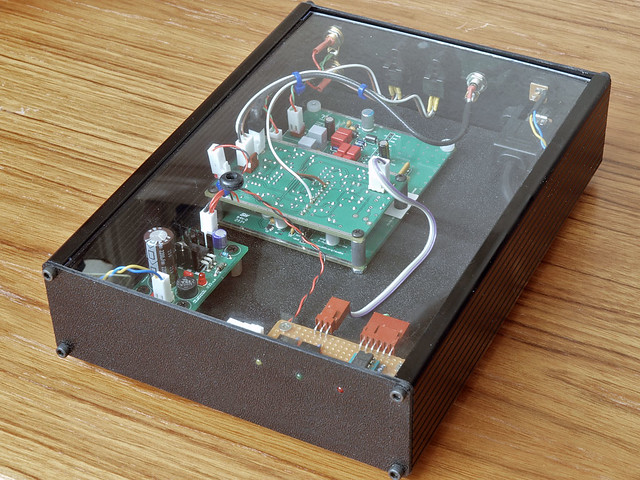
an spdif 'pod' switch:
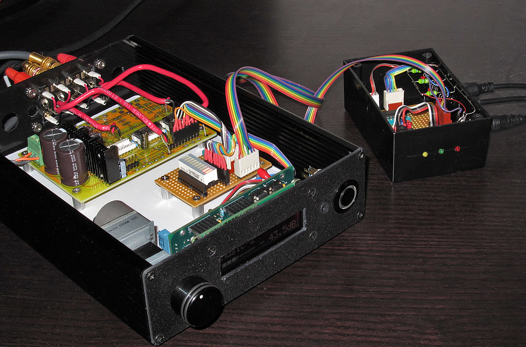
I like the idea of a remote pod. a wire concentrator that can be thrown on the floor or behind a cabinet or just out of the way!
its linked to the main preamp via a simple i2c cable (power,gnd, clock, data). nothing special.
the lcduino can be configured to talk to 2 different kinds of i/o switch. one is the relay based delta2 that gives 8 assignable relay ports, 'punchable' to the input or output bus (pick and choose). the other is an spdif switch like this one here. you send it a 3 bit a0,a1,a2 addr and it picks 1 of the 8 and sends it thru. simple ttl stuff that works just fine for spdif. 5v toslinks make the job even easier.
on the side are leds that map 1:1 with the input ports. those leds are software settable and when the system wants to, it shows those leds as the one that is currently active being bright and the others off. when the whole system is on standby, all leds are off. even when the system is up and running but put into 'dark theater mode' all leds go off but all functions still work.
you can assign analog volume levels to the i/o ports. if one spdif line was from your tv audio and another from mp3 player, you may want to have one level control run hotter than the other. this has a memory that keeps track of where you were at just before you switch to another port. you always have the last-used vol setting - even for a digital i/o port!
its an early POC but plans will come shortly. software support is already there in alpha test and is planned to be released (open source) really soon (weeks).
I love having a PGA vol controller and an spdif switcher all integrated, with sleep timer, named port screens and various display modes. hopefully others will see value in this architecture and module series.
an spdif 'pod' switch:
I like the idea of a remote pod. a wire concentrator that can be thrown on the floor or behind a cabinet or just out of the way!
its linked to the main preamp via a simple i2c cable (power,gnd, clock, data). nothing special.
the lcduino can be configured to talk to 2 different kinds of i/o switch. one is the relay based delta2 that gives 8 assignable relay ports, 'punchable' to the input or output bus (pick and choose). the other is an spdif switch like this one here. you send it a 3 bit a0,a1,a2 addr and it picks 1 of the 8 and sends it thru. simple ttl stuff that works just fine for spdif. 5v toslinks make the job even easier.
on the side are leds that map 1:1 with the input ports. those leds are software settable and when the system wants to, it shows those leds as the one that is currently active being bright and the others off. when the whole system is on standby, all leds are off. even when the system is up and running but put into 'dark theater mode' all leds go off but all functions still work.
you can assign analog volume levels to the i/o ports. if one spdif line was from your tv audio and another from mp3 player, you may want to have one level control run hotter than the other. this has a memory that keeps track of where you were at just before you switch to another port. you always have the last-used vol setting - even for a digital i/o port!
its an early POC but plans will come shortly. software support is already there in alpha test and is planned to be released (open source) really soon (weeks).
I love having a PGA vol controller and an spdif switcher all integrated, with sleep timer, named port screens and various display modes. hopefully others will see value in this architecture and module series.
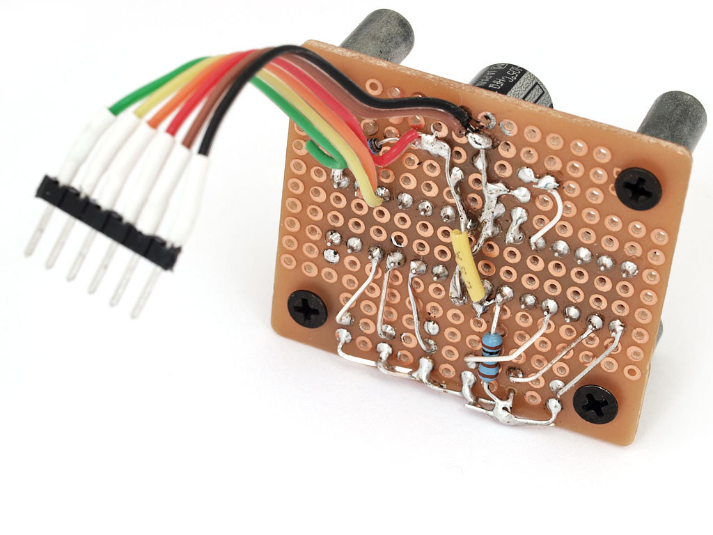
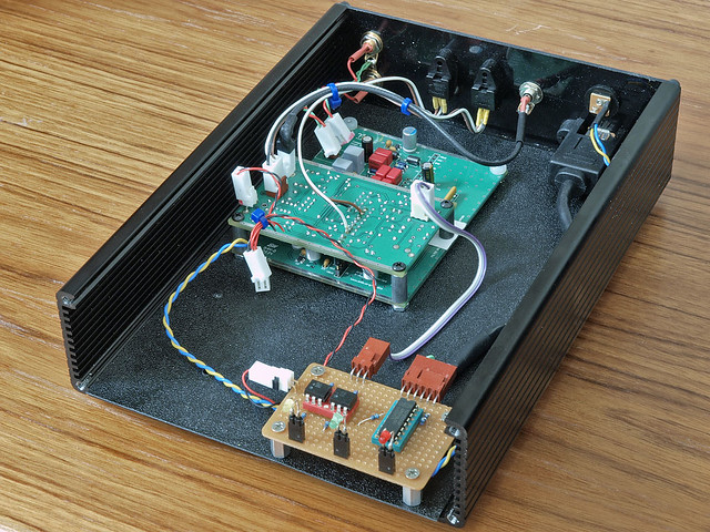
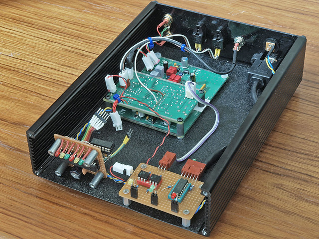
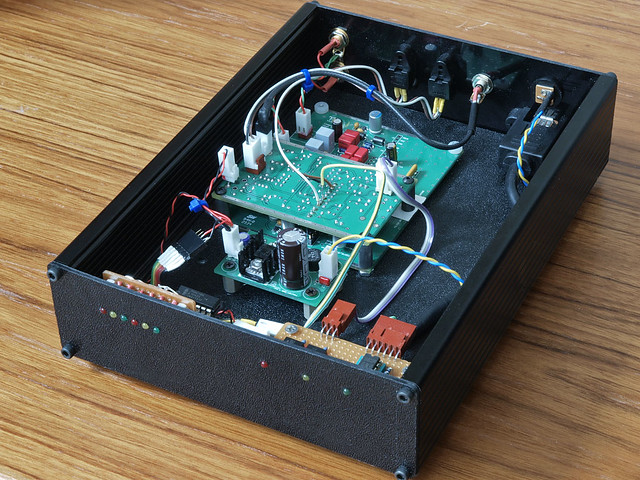
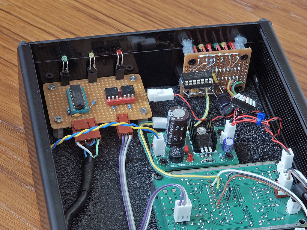
more pics. no schematic yet, I went direct to perf board; but I'll draw one up later on. this will at least get the idea across.
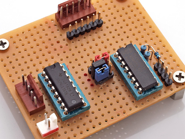
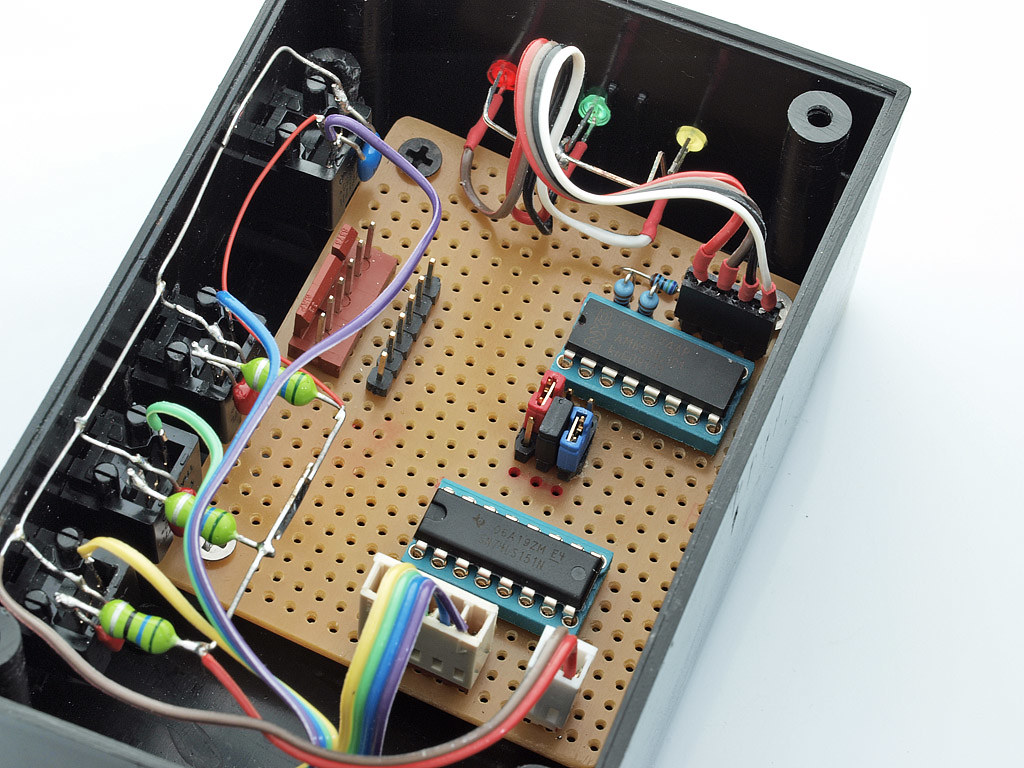
some notes, referring to the pcb top photo, component side:
top/right pair of connectors (6pin) carry i2c. pinout is same as LCDuino: 2 pins at one end for power (paralleled), 2 for gnd, then data then clock. the keyed red connector is the same as the unkeyed 'courtesy' pass-thru, as I call it") it lets me daisy chain the i2c connection if I need to.
it lets me daisy chain the i2c connection if I need to.
below that are the red/black/blue jumpers. you can set a 3bit user address on the port expander, the chip to its right (pcf8574). you can know this PE chip by its addr block to the top/left area and its i2c pullups in blue tombstones to the right, near the vcc power pin.
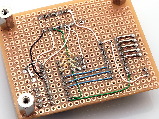
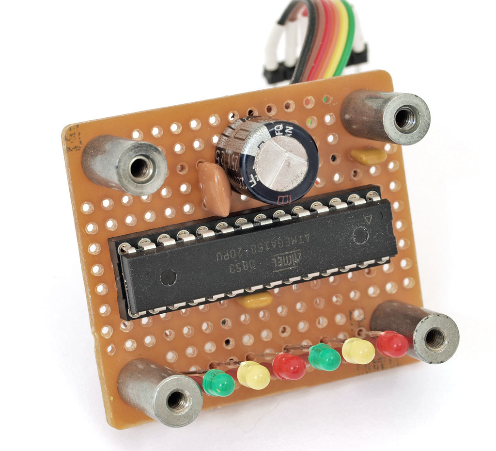
to the right of that chip are 4 nonkeyed jumpers. one is common vcc and the other 3 are for the software settable leds. the pcf chip loves to sink current but not source; so I dangle the leds off vcc and connect to ground to activate. this also means that my logic at the controller side has to invert and send 1's to all leds that should be OFF. those leds occupy the upper bits in the 8bit byte. the lower 2 bits or 3 bits contain the binary encoding of the port you want to select (001, 010, 011, etc). those are the bits0..bit3 and if you look at the wiring side, you will see the direct blue wires going straight across from the PE chip to the 'switch' chip.
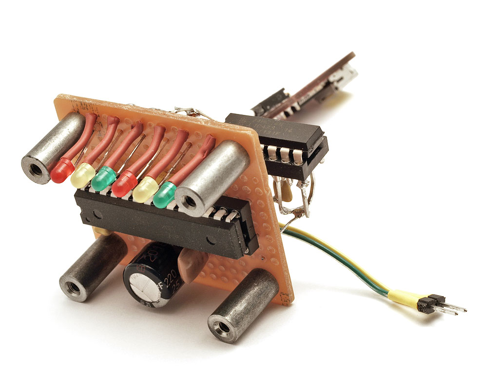
the switch chip is bog standard ttl stuff; 74151 style. I plan to try various 'ALS' and other tech to see if it matters but I suspect it won't matter at all. the swtich chip has 2 connectors; one with red marker (lol) to send power and gnd to the toslink blocks. the other keyed connector is the 1 output (bottom pin closer to the power white molex) and 4 input pins. those go direct to the toslink blocks.
with the leds being a software abstraction, you can do things like this:
or:
here I take the 'bitmask' version of the port number (ports start at port0) and shift that up into the upper area of the byte for 'led display purposes'. the lower portion of the byte contains the binary encoding of the port #, intended not for humans but for the 74151's benefit
this software trick saved me having to decode binary into a 1-of-n mask just for the leds and it also lets me turn all leds off when the user presses the 'all lights out' remote button. if all lights are off, you could press an ID button and the leds can come up, show themselves, then turn off after a delay.
some notes, referring to the pcb top photo, component side:
top/right pair of connectors (6pin) carry i2c. pinout is same as LCDuino: 2 pins at one end for power (paralleled), 2 for gnd, then data then clock. the keyed red connector is the same as the unkeyed 'courtesy' pass-thru, as I call it
it lets me daisy chain the i2c connection if I need to.below that are the red/black/blue jumpers. you can set a 3bit user address on the port expander, the chip to its right (pcf8574). you can know this PE chip by its addr block to the top/left area and its i2c pullups in blue tombstones to the right, near the vcc power pin.
to the right of that chip are 4 nonkeyed jumpers. one is common vcc and the other 3 are for the software settable leds. the pcf chip loves to sink current but not source; so I dangle the leds off vcc and connect to ground to activate. this also means that my logic at the controller side has to invert and send 1's to all leds that should be OFF. those leds occupy the upper bits in the 8bit byte. the lower 2 bits or 3 bits contain the binary encoding of the port you want to select (001, 010, 011, etc). those are the bits0..bit3 and if you look at the wiring side, you will see the direct blue wires going straight across from the PE chip to the 'switch' chip.
the switch chip is bog standard ttl stuff; 74151 style. I plan to try various 'ALS' and other tech to see if it matters but I suspect it won't matter at all. the swtich chip has 2 connectors; one with red marker (lol) to send power and gnd to the toslink blocks. the other keyed connector is the 1 output (bottom pin closer to the power white molex) and 4 input pins. those go direct to the toslink blocks.
with the leds being a software abstraction, you can do things like this:
Code:
  // force the upper bits to be all 1 (which turns OFF our leds!)
   pcf.write(7, B11110000 | input_selector );
or:
Code:
    inverted_shifted_mask = ~(1 << (input_selector+4));
    inverted_shifted_mask &= B11110000;  // only keep the top 4 bits
    pcf.write(7, inverted_shifted_mask | input_selector );
here I take the 'bitmask' version of the port number (ports start at port0) and shift that up into the upper area of the byte for 'led display purposes'. the lower portion of the byte contains the binary encoding of the port #, intended not for humans but for the 74151's benefit
this software trick saved me having to decode binary into a 1-of-n mask just for the leds and it also lets me turn all leds off when the user presses the 'all lights out' remote button. if all lights are off, you could press an ID button and the leds can come up, show themselves, then turn off after a delay.
absolutely! you could completely map 1 input to a 'bus' and then have the outputs be bit-addressible in what I call 'multi-mode'. on my controller firmware, I support input selection (gui/web guys call that 'radio button' behavior) and also output selection (both styles; radio-button and also toggle-button, which is what you are asking for). in toggle button, you press the output port # (on the IR remote) to toggle it on/off. all ports that are on, still stay on but yours toggles states. the user can pick 'multi mode' and get that behavior on output_ports OR he can go to single-mode and have outputs feel like inputs, in that its 1-of-n radio button style.
the switch would be a bit different but the port expander would be the same. I would have the single input pin go to a 'bus' concept and then each output port (repeater port, essentially) would go thru an AND gate and either pass the data or not pass the data (assert all 0 or all 1 and not let pulses thru to the toslink senders). not at all hard. maybe I'll build one of those, too, as POC
the switch would be a bit different but the port expander would be the same. I would have the single input pin go to a 'bus' concept and then each output port (repeater port, essentially) would go thru an AND gate and either pass the data or not pass the data (assert all 0 or all 1 and not let pulses thru to the toslink senders). not at all hard. maybe I'll build one of those, too, as POC
thinking more about the implementation of the more complex cross-connect switch.
if you wanted to have more manageable outputs, perhaps each output would have its own private 1-of-8 input selector. there would be 8 internal 'send busses' which come from the 8 possible input ports (toslink TORX blocks). each output 1-of-n would share all 8 TORX outputs, so depending on fanout, buffering may be needed (not sure).
1-of-8 selectors need 3 bits. if you are ok with 4 input ports, then you can now get by with 2 bits. the # of input ports you allow defines the n part of the '1-of-n' and also the # of bits needed in addressing.
if you go with 4 input ports, max, that's 2 bits of address. how many of those will fit in a byte? 4 of them. and so if you are ok with having 4 output ports, you could do this all in a single 8-bit port expander like the PCF chip I used. you take the parts of its 8bit byte (the pin numbers) and send a pair to one 1-of-n chip and then another pair to another chip, etc.
you formulate the byte you want from the user's setup. the user somehow defined the punchdown relationships (I want outputs 3,4,5 to be attached to input 1, etc) and so you make the binary mask from that describing all 4 outputs and their 1-of-n binary addresses and send that off to the PE chip. if the user changes one 'knob' position, you recalculate the new byte and send it out. any bits that are the same can stay the same, you do the right logical OR or AND as needed.
this assumes you want a multi by multi switch. if you want simpler, perhaps more optimizations can be done.
code is finished. you can get a copy of the .zip file (source that is buildable on any arduino IDE) here: The LCDuino-1 Display I/O Processor (follow the 'download' link on the left).
'spdif switch' mode is just the software running with no volume control engines configured. go into the config menu (on the lcd, using the IR remote) and set the vol engine to 'n/a' and set the i/o engine to 's-addr' and you should be able to name ports and have the names show up on the top line as you change inputs.
'spdif switch' mode is just the software running with no volume control engines configured. go into the config menu (on the lcd, using the IR remote) and set the vol engine to 'n/a' and set the i/o engine to 's-addr' and you should be able to name ports and have the names show up on the top line as you change inputs.
I would like to get a samplerate display. its not easily done. there is no receiver to decode the stream and show any base frequency.
however, it might be possible to put a freq->voltage converter in there and roughly map the basebase freq (as sampled) to a samplerate frequ. there are only a few standard SR's so it might not be too hard to hack it like this.
currently though, nothing 'sniffs' the data; its just passed thru as-is. but I do like the idea and have thought about it for a while. its just beyond the layer-1 nature of this design, at the moment.
you could change the code so that it writes the binary mask value instead of PULSING the mask out. that would be the only difference. it would probably cut the amount of code needed by removing a good 50-100 lines, making it even simpler!
what I didn't like about regular relays is that they require higher power due to the fact that they are voltage-on to activate them. but they are MUCH easier to buy, that's for sure!
what I didn't like about regular relays is that they require higher power due to the fact that they are voltage-on to activate them. but they are MUCH easier to buy, that's for sure!
today I created an AES3 output on the spdif switch. or, something close to it, at least not a re-encode of the bitstream but just a more 5v-based balanced output.
all I had to do was take a ttl level output from the switch chip. I used a 74151 that has both a Y and ~Y output, so use one for opto out and one for the next stage, the AES3 out. spdif doesn't care about bit polarity at the raw 'wire' level so its fine.
next stage is a 75als191 (or ua9638) rs422 line driver and a pulse trafo. from the 75191 I used a series R (50-200 ohms, not too critical in actual practice) and then the pulse trafo. ideally a 1:1.2 ratio to match 75/110 would be best but to be honest, I doubt I have anything like a real 75ohms off my ttl switch chip I did have a 110R in parallel with the secondary of the pulse and then that went to the twisted pair and off to the DCX2496, which was my ultimate target for the spdif switch.
things work fine. it costed a driver chip (8pin dip), an inexpensive pulse transformer ($3 or so) and an R or two. plus whatever jack you want to use (I could only fit a 1/4" TRS jack but luckily there are common TRS-XLR cables and I used an existing commercial audio cable).
I can't speak about jitter in this build (hand made proto board stuffed in suboptimal plastic chassis) but I'm not hearing any sound issues from the DCX (my only aes3 box in the house I can test with).
I'm getting closer to making a PCB. will update the thread if/when that happens.
not a re-encode of the bitstream but just a more 5v-based balanced output.all I had to do was take a ttl level output from the switch chip. I used a 74151 that has both a Y and ~Y output, so use one for opto out and one for the next stage, the AES3 out. spdif doesn't care about bit polarity at the raw 'wire' level so its fine.
next stage is a 75als191 (or ua9638) rs422 line driver and a pulse trafo. from the 75191 I used a series R (50-200 ohms, not too critical in actual practice) and then the pulse trafo. ideally a 1:1.2 ratio to match 75/110 would be best but to be honest, I doubt I have anything like a real 75ohms off my ttl switch chip
I did have a 110R in parallel with the secondary of the pulse and then that went to the twisted pair and off to the DCX2496, which was my ultimate target for the spdif switch.things work fine. it costed a driver chip (8pin dip), an inexpensive pulse transformer ($3 or so) and an R or two. plus whatever jack you want to use (I could only fit a 1/4" TRS jack but luckily there are common TRS-XLR cables and I used an existing commercial audio cable).
I can't speak about jitter in this build (hand made proto board stuffed in suboptimal plastic chassis) but I'm not hearing any sound issues from the DCX (my only aes3 box in the house I can test with).
I'm getting closer to making a PCB. will update the thread if/when that happens.
I seem to have luck with spdif. wiring never seems to be critical and receivers always lock on. I know, I know, the impedance gods will curse me for saying so. the audio sounds fine to me and no matter what I do, it never gets better or worse.
the proto was also just hand wired; but again, spdif seems to just plain work no matter what wire or connectors I use.
the proto was also just hand wired; but again, spdif seems to just plain work no matter what wire or connectors I use.
update: I may add something like this to my spdif switch display. its the spdif sample rate that is directly read off of the decoded i2s LR-clock line. here's my test bed that has the wolfson wm8804 spdif receiver; then it splits out i2s to a 3wire ribbon cable going to a test junker dac (not relevant here). the red highlight shows a schmitt trigger on the word clock that feeds my arduino (to a spare digital-in pin). the arduino does a software frequency counter trick and shows the value it counted. I did 2 test runs to see how close the software freq counter was to my good one. it was good enough so that I can truncate some digits and show the native rate. (I'll test at 96k and higher when I get a chance).

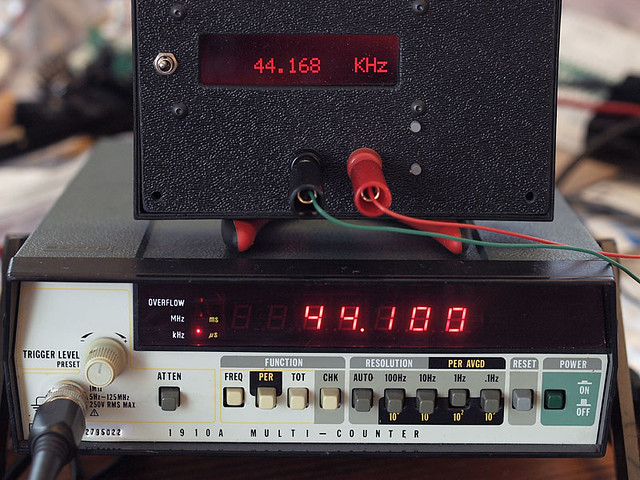
I've been wanting to do this for a long time but it always needed an spdif receiver. so, when I built one up for another project, I decided to revisit the SR display problem again.
it came in handy, already, too; I found when my sound card was sending movies out at 44.1 and music at 48k I had to use ASIO to get my sound card to be native at 44.1 again. I never knew this until I just checked. the device already made itself worth its effort.
An externally hosted image should be here but it was not working when we last tested it.
I've been wanting to do this for a long time but it always needed an spdif receiver. so, when I built one up for another project, I decided to revisit the SR display problem again.
it came in handy, already, too; I found when my sound card was sending movies out at 44.1 and music at 48k
I had to use ASIO to get my sound card to be native at 44.1 again. I never knew this until I just checked. the device already made itself worth its effort.more progress.

and a really stupid and boring video demo of it:
http://www.netstuff.org/spdif/spdif_led_meter_1.mp4
this started out as just a test tool, but I'm wondering if its got potential as a small purpose-built spdif rate-meter on its own. its very low cost and uses a 168 or 328 series arduino and some misc junk r/c parts you have lying around.
yes, I do plan to have software control for the 8804/8805. its mostly coded but I have not gone beyond 'it compiles'. I plan to get back to the software driver for it, though.
the only things I want to use i2s for are for getting the samplerate via decoding to lr-clock; and if its convenient, I'd like to throw in a small dac chip just because the i2s lines *are* there (grin). I tried a pcm5102 and was not impressed. same with the ESS equivalent dac chip. I'm going to try a few more 'easy dac chips' but this is not a focus and not meant to be a replacement for a proper external dac.
its true that I want to stay spdif in and out. whether its 'the best' data transport for digital audio is not my call to make; the fact is that lots of gear use spdif and having a remote controllable hub to switch them is useful, I think.
for the cost of 1 switch gang, I found I can provide two and give 2 buses for output, independant of each other. a use-case is a 'monitor' out and a 'record' out. each switch input gets a buffered copy of the stream and each switch is addressible on its own. the rest is up to the main processor; its that guy who takes the user request such as 'play my squeezebox' and it knows that its on digital switch #1, port #3 and we have to route thru analog-in #5 on the preamp. all that lookup-table work is taken care of by the main lcduino and the switch just gets told to set its A gang to 'a' and its B gang to 'b'. and if there is a dac chip onboard, I'd tie it to one of those switched outputs and give the user a line-out in addition to an spdif-select-out.
integrated the samplerate display into an existing DAC:
so far, the proof of concept works! I found that my sound card was not even set to 48k for movies, for some reason. everything was being resampled to 44.1 (isn't THAT a switch, lol!). I found the sound card setting, changed it and now music comes out at 44.1 and movies at 48k (stereo downmix). it already earned its keep this first time I used it.
so far, the proof of concept works! I found that my sound card was not even set to 48k for movies, for some reason. everything was being resampled to 44.1 (isn't THAT a switch, lol!). I found the sound card setting, changed it and now music comes out at 44.1 and movies at 48k (stereo downmix). it already earned its keep this first time I used it.
- Status
- This old topic is closed. If you want to reopen this topic, contact a moderator using the "Report Post" button.
- Home
- Source & Line
- Digital Line Level
- spdif switch module for LCDuino