Hi
I am building a NOS power dac, I have dutifully taken on board the perceived wisdom that it should be down 3.5 dB by 20kHz. I can measure with the ARTA, using m-audio transit at 44.1K and I get -3.5dB at 20K, measuring same signal with Sound Technology 1700B distortion analyser I get -0.6dB.... on the scope the pk-pk is constant for all frequencies.
f _______ST______pkpk__arta____arta normalised
100Hz___0db______8.6_ -16.8 fs__0dB
1kHz____0dB______8.6_ -16.8 fs__0dB
10kHz___-0.2dB___8.6__ -17.6 fs__-0.8dB
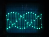
14kHz___-0.4dB___8.6__ -18.4 fs__-1.6 dB pic
20kHz___-0.6dB___8.6__ -20.1 fs__-3.3 dB
any bright ideas, or is this just rms kind of thing, apparently the 1700b meter is “average” responding...
thanks h.
pics, arta response and scope trace of 14kHz
I am building a NOS power dac, I have dutifully taken on board the perceived wisdom that it should be down 3.5 dB by 20kHz. I can measure with the ARTA, using m-audio transit at 44.1K and I get -3.5dB at 20K, measuring same signal with Sound Technology 1700B distortion analyser I get -0.6dB.... on the scope the pk-pk is constant for all frequencies.
f _______ST______pkpk__arta____arta normalised
100Hz___0db______8.6_ -16.8 fs__0dB
1kHz____0dB______8.6_ -16.8 fs__0dB
10kHz___-0.2dB___8.6__ -17.6 fs__-0.8dB
14kHz___-0.4dB___8.6__ -18.4 fs__-1.6 dB pic
20kHz___-0.6dB___8.6__ -20.1 fs__-3.3 dB
any bright ideas, or is this just rms kind of thing, apparently the 1700b meter is “average” responding...
thanks h.
pics, arta response and scope trace of 14kHz
Attachments
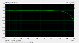
The -3.16dB @ 20kHz roll-off with NOS 44.1k sample rate data is due to what's called the "zeroth order-hold" ( sample-and-hold) functioning of the resistor-ladder, or non-sigma-delta, class of DACs (PCM56, PCM1704, TDA1451, TDA1453, AD1865, etc.) utilized with NOS.
I'm not sure why you are having a disprecpency between your measurement systems, but that -3.5dB result using the M-AUDIO and ARTA 'Steps' software is the more correct of those two.
I use ARTA with an M-AUDIO Audiophile 192kHz PCI card.
I'm not sure why you are having a disprecpency between your measurement systems, but that -3.5dB result using the M-AUDIO and ARTA 'Steps' software is the more correct of those two.
I use ARTA with an M-AUDIO Audiophile 192kHz PCI card.
Last edited:
I have now read up on "zeroth order hold" unfortunately no one told RMS meter, which also reads -0.6dB at 20kHz. but.....
I have a theory:
The meter is reading an unfiltered signal, where as the m-audio sampling @ 44.1kHz has not got a hope of capturing the higher frequencies, A quick test of comparing sine and square using an true RMS multimeter gives 2.767 V square, 2.056V for sine, 20log(2.056/2.767) gives 2.57dB, add that to the -0.6 gives -3.2 dB, I'll buy that as a possible explanation.
Yes, as well as the 20kHz signal you will also have a 24.1kHz image. The meter may be lumping them together.
Any DAC which uses sample-and-hold (i.e. almost all DACs) wll give this sinc frequency response, irrespective of the internal DAC technology. An oversampling system will normally compensate for it by adjusting the digital filters, and in any case will have less of it because it is working at a higher sampling rate. A simple NOS has to choose between accepting the frequency droop, or introducing extra phase shift in attempting to correct it.
Any DAC which uses sample-and-hold (i.e. almost all DACs) wll give this sinc frequency response, irrespective of the internal DAC technology. An oversampling system will normally compensate for it by adjusting the digital filters, and in any case will have less of it because it is working at a higher sampling rate. A simple NOS has to choose between accepting the frequency droop, or introducing extra phase shift in attempting to correct it.
How I learned to love THD
I am not confused any more, really done it now, an amplifier with 47% distortion and its the best sounding one I have ever made (and I have made a few).
There are two versions of reality occurring here, the sanitised BS world of digital (44.1kHz sampling rate) measurement, and the real, messy world of (1970s) analogue... you take your choice. You either choose 20kHz at -3.5dB with 0.4% THD (in my case) or 20kHz at -0.5dB and 47% THD. My ears tell me the latter to be honest, and the best bit, it sounds good!!
h
Attachments
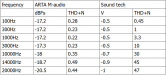
You either choose 20kHz at -3.5dB with 0.4% THD (in my case) or 20kHz at -0.5dB and 47% THD.
Aliasing isn't harmonic (the 'H' in THD) distortion but it is distortion nevertheless.
It is noise. Any NOS without brickwall filter will generate audio signals that are not present in the original. If they are corellated with the signal, there are called harmonic distortion, if they are uncorellated, they are called noise.
THD+N is just adding the influence of the distortion with the one of the noise, I don't see whay won't be appropiate.
Unless you want to hide the reality")
THD+N is just adding the influence of the distortion with the one of the noise, I don't see whay won't be appropiate.
Unless you want to hide the reality
Last edited:
No, to be called harmonic distortion it needs to be more than correlated it also needs to be at a harmonic frequency. You could call the image intermodulation, because that is what it is. Fortunately our ears are not sensitive to pitch at 20kHz, so a percussive sound which includes 20kHz or 24.1kHz might sound similar - I suspect this is how simple NOS works.
You have not demonstrated that "47% THD" is OK, and therefore THD is meaningless. You may have shown that a transient at 20kHz and -3.5dB plus a 47% image at 24.1kHz is almost indistinguishable from the (correct) 20kHz transient at 0dB, as both signals contain about the same HF energy.
You have not demonstrated that "47% THD" is OK, and therefore THD is meaningless. You may have shown that a transient at 20kHz and -3.5dB plus a 47% image at 24.1kHz is almost indistinguishable from the (correct) 20kHz transient at 0dB, as both signals contain about the same HF energy.
Hi,
Thanks for the interesting comments. Re trying to prove worthless ness of THD, I am not particularly out to do that, it certainly has its uses. The wave forms coming out of the nos dac are a bit yucky – qualify, 44.1kHz attempts at doing a sine wave of >10kHz look a bit yucky if you look closely at them. And if we step back and look at the (my) distortion analyser as giving me a ratio of “desired” sine wave to everything else, and maybe call it distortion, then I find it quite educational, (in my little adventure) (my first dac) to observe the amount of supplemental crud that is put out, and put a number on it. I was slightly surprised / disappointed when doing the above test at how quickly the “distortion” ramped up. Anyway. Dragged out semi-retired (RF) spectrum analyser, and had a look at the emissions for various frequencies. Picture not very clear, but imagine the span is 0-1MHz horizontal, and 10dB per division vertical. Interesting (but now expected) how much the harmonics increase as the frequency increases. Plots for 1 and 20kHz.
Thanks for the interesting comments. Re trying to prove worthless ness of THD, I am not particularly out to do that, it certainly has its uses. The wave forms coming out of the nos dac are a bit yucky – qualify, 44.1kHz attempts at doing a sine wave of >10kHz look a bit yucky if you look closely at them. And if we step back and look at the (my) distortion analyser as giving me a ratio of “desired” sine wave to everything else, and maybe call it distortion, then I find it quite educational, (in my little adventure) (my first dac) to observe the amount of supplemental crud that is put out, and put a number on it. I was slightly surprised / disappointed when doing the above test at how quickly the “distortion” ramped up. Anyway. Dragged out semi-retired (RF) spectrum analyser, and had a look at the emissions for various frequencies. Picture not very clear, but imagine the span is 0-1MHz horizontal, and 10dB per division vertical. Interesting (but now expected) how much the harmonics increase as the frequency increases. Plots for 1 and 20kHz.
Attachments
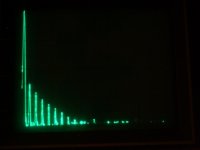
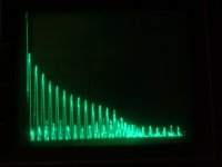
What you are seeing there are not harmonics, but images. They are low for 1kHz because its images are all near the sampling frequency and so near the zeroes of the sinc filter response. 20kHz images are higher because they are well away from nulls in the response. An alternative (time domain) way of looking at it is that a 1kHz output from the DAC looks on a scope like a slightly modified sine wave, but a 20kHz looks very different. The difference between a perfect sine wave and the DAC output is what the images consist of.
In a conventional OS DAC, these images would be filtered away by the brick-wall reconstruction filter.
In a conventional OS DAC, these images would be filtered away by the brick-wall reconstruction filter.
I am not confused any more, really done it now, an amplifier with 47% distortion and its the best sounding one I have ever made (and I have made a few).
There are two versions of reality occurring here, the sanitised BS world of digital (44.1kHz sampling rate) measurement, and the real, messy world of (1970s) analogue... you take your choice. You either choose 20kHz at -3.5dB with 0.4% THD (in my case) or 20kHz at -0.5dB and 47% THD. My ears tell me the latter to be honest, and the best bit, it sounds good!!
h
I am dealing with a similar issue on a TDA1543 DAC project I am working on at the moment.
From what I can see measuring THD vs. Frequency on a NOS DAC will give you garbage due to all of the harmonics caused by NOS. Is there any way to meaure the THD of a NOS DAC with a 10Khz 0dB sinewave input? The output is "garbage" -but so what because music does not consist of a sinewave. ?
Why not? But not with the traditional THD meter that filters the fundamental and measures the rest. You have to use an FFT analyzer, measure the 2nd, 3rd, etc components and calculate. In your case measure the 20 kHz, 30 kHz, 40 kHz components (not above) and calculate the THD. But since the fundamental is a first-order hold (~ square) signal, it has natural harmonics. Separating these high amplitude natural harmonics from true distortion components will be impossible IMHO.Is there any way to meaure the THD of a NOS DAC with a 10Khz 0dB sinewave input?
If you have a spectrum analyser you can measure the second harmonic of 10kHz, but higher harmonics will be seriously mixed up with images. So I think the answer is no, you can't measure THD for 10kHz with a NOS DAC. Or perhaps more accurately, THD for 10kHz on a NOS DAC is not a useful concept. It is not very useful for OS DAC either, as the brick-wall reconstitution filter will remove 3rd harmonic and above.
You could measure for 1kHz, and assume the DAC nonlinearity will not depend too much on frequency.
The general principle is that THD only has meaning for any system if the test frequency is sufficiently low that a significant number of harmonics fall within the system bandwidth. On this basis 10kHz THD for an amplifier does not have much meaning.
Better to measure intermodulation. This also checks linearity, but only requires that the inputs be within the bandwidth and (for second-order) their difference too. You can measure 10+11kHz IMD for a DAC and it is a useful thing to know. Feed in 10+11kHz (or whatever similar freqs you have). Look for 1kHz (second-order difference) and 9+12kHz (third-order products) in the output.
- Status
- This old topic is closed. If you want to reopen this topic, contact a moderator using the "Report Post" button.
- Home
- Source & Line
- Digital Line Level
- confused about -3.5db @20k on nos dac build