I wasnt suggesting using those chips, just that you might look at making sure whatever the device is that is next can have its common mode input voltage lifted above ground, be it chip, fet whatever and pick the highest gM part
also I really do suggest using current mode if you can, on top of measuring better it sounds much better to my ears
also I really do suggest using current mode if you can, on top of measuring better it sounds much better to my ears
The 9023's outputs are ground referenced per the part's headline spec. (So are the 9022's.) It would be an unusual op amp which couldn't handle the 1.65V common mode of the other ESS DACs.
ESS's distinction between voltage and current mode is unclear. Implementing the current mode schematics with 49720s imposes a load impedance of 60k for figure 1 of the app note and 30k for figure 3. As the resistor values in the voltage mode output schematics in the 9006 and 9008 datasheets are unlabeled it's difficult to reason about how the DACs are responding to output loading. If one assumes it's a unity gain buffer workback on the noise floor suggests the resistors are a few hundred ohms. Increasing that to a more typical 1k would impose a more friendly load on the DAC and 10k probably wouldn't be a problem. For example, if one implements a low cost fully differential op amp by using a cheap dual op amp putting 10k resistors in the feedback nets results in the DAC seeing a 20k load. I would be surprised if that measured much different from figure 3 of the app note, and the figure 3 results are pretty decent.
Can you share what load impedances you have tried and how the measured performance varies between them or are you under NDA?
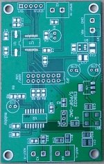
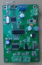
ES9023 PCB with WM8804
I made a PCB to evaluate ES9022/23 with WM8804 SPDIF. I have got the draft version (one error in the WM8804 section). The board has I2S header and separate power supply for ES9022, so the whole WM8804 section can be ignored.
I have been listening with it for few days and it sounds great.
I have got about 4 spare boards and ES9022 if someone wants to evaluate it. The PCB costed about $10 and DAC $4. Let me know if anyone want them.
-Subbu
> I have been listening with it for few days and it sounds great.
Cannot agree more. But have you actually try the ES9023 ?
See also :
http://www.diyaudio.com/forums/digi...ng-new-ess-vout-dac-es9022-2.html#post2525805
http://www.diyaudio.com/forums/digi...ransport-shigaclone-story-93.html#post2534884
Patrick
Cannot agree more. But have you actually try the ES9023 ?
See also :
http://www.diyaudio.com/forums/digi...ng-new-ess-vout-dac-es9022-2.html#post2525805
http://www.diyaudio.com/forums/digi...ransport-shigaclone-story-93.html#post2534884
Patrick
how ess 9023/22 sound compared to cs4397
Good i hope!
") )
)(i'm buying a few)
more food for thought....
... and what about the new TI PCM5102?
Audio Converter - Audio DAC - PCM5102 - TI.com
Brand new low cost dac. It seems to be a "copy" of the ES9023 with some pros and cons.
No, pls, I've just received the ESS dacs and I didn't start to use them!
... and what about the new TI PCM5102?
Audio Converter - Audio DAC - PCM5102 - TI.com
Brand new low cost dac. It seems to be a "copy" of the ES9023 with some pros and cons.
No, pls, I've just received the ESS dacs and I didn't start to use them!
3.5v on the 9022?
Does anyone know if the 9022 will tolerate 3.5v (just a hair over the 3.3v +5% of 3.46v)?
This voltage is in the 'recommended operating conditions' section of the datasheet, not the 'absolute maximums'.
TIA!
Greg in Mississippi
Are you running 3.6V on the 9023 ?
Patrick
Does anyone know if the 9022 will tolerate 3.5v (just a hair over the 3.3v +5% of 3.46v)?
This voltage is in the 'recommended operating conditions' section of the datasheet, not the 'absolute maximums'.
TIA!
Greg in Mississippi
Patrick,
could you kindly mail me a copy of the ES9023 datasheet?
My main question is whether I need to include a resistor in series with the output
before a 10nF cap to ground. And if so what value. The dac drives a S&B TX102 transformer volume control (10K minimum impedance).
Many thanks in advance
Giulio
could you kindly mail me a copy of the ES9023 datasheet?
My main question is whether I need to include a resistor in series with the output
before a 10nF cap to ground. And if so what value. The dac drives a S&B TX102 transformer volume control (10K minimum impedance).
Many thanks in advance
Giulio
Thanks for that.>
No need.
Got it from Ismosys.For datasheet please make request at ESS distributor.
giulio
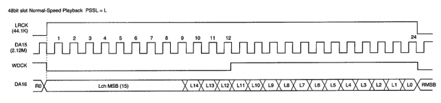
Hi guys. I want to try SE9023 as a replacement to an ordinary delta-sigma DAC from Cirrus Logic. This one will be linked to Sony's CXD2515Q. Those two chips are not directly compatible. The CXD2515Q chip outputs 16 bit right-justified standard format MSB first. This is the output data from CXD2515Q:

ES9023 will be used at 384fs fed with 16.9344MHz and set to left-justified format. This is how it looks like:
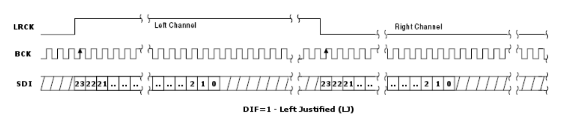
So from what I see, I only need to delay the LRCK by 8 cycles to make things work together. Am I correct?
Regards, Venci.
ES9023 will be used at 384fs fed with 16.9344MHz and set to left-justified format. This is how it looks like:
So from what I see, I only need to delay the LRCK by 8 cycles to make things work together. Am I correct?
Regards, Venci.
Attachments

- Status
- This old topic is closed. If you want to reopen this topic, contact a moderator using the "Report Post" button.
- Home
- Source & Line
- Digital Line Level
- ESS ES9023 Sabre Premier DAC with integrated op amp